Vibration suppression structure
A folded plate structure and vibration plate technology, applied in the direction of shock absorber, inertial effect shock absorber, spring/shock absorber, etc. Large size, heavy weight and other problems, to avoid the design frequency offset, broaden the working frequency band, reduce the working frequency
- Summary
- Abstract
- Description
- Claims
- Application Information
AI Technical Summary
Problems solved by technology
Method used
Image

Examples
Embodiment 1
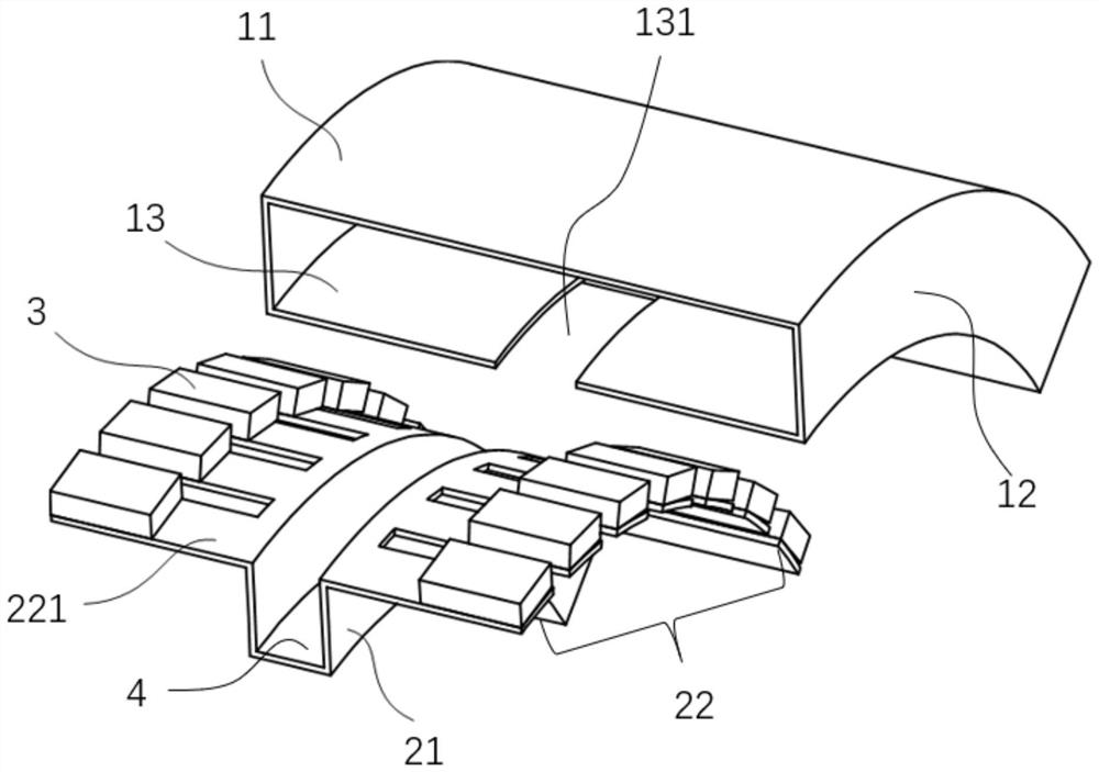
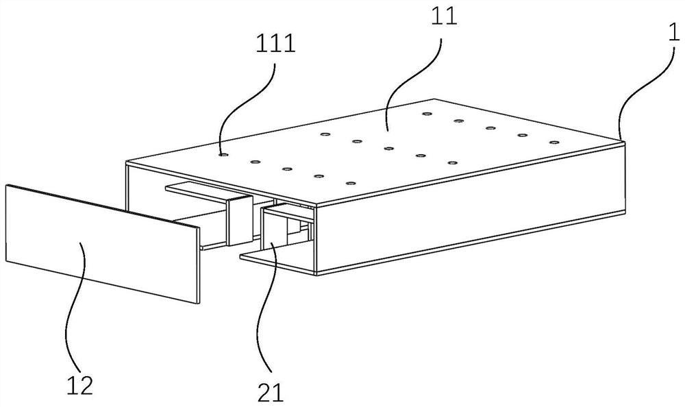
[0045] The invention provides a suppressing structure in which the resonator is placed in the shell, such as Figure 1-7 As shown, it includes the shell 1 and the vibrating plate 2. The vibrating plate 2 is the main component for suppressing low-frequency vibration. Part or all of the vibrating plate 2 is placed in the shell 1. The shell 1 can effectively protect the main resonance of the vibrating plate 2. structure, to avoid the design frequency shift caused by the resonant structure being affected by external force, and improve the low-frequency vibration suppression effect. specifically:
[0046] The housing 1 is mainly a cavity structure surrounded by a top plate 11 , a side plate 12 and a bottom plate 13 , and the side plate 12 is located between the top plate 11 and the bottom plate 13 . The shape of the shell 1 surrounding the cavity structure can be square, cylindrical, truncated cone, arc, irregular, etc., mainly depending on the structure that needs low-frequency v...
Embodiment 2
[0050] Embodiment 2 is formed on the basis of Embodiment 1, and the vibration suppression performance of the vibration suppression structure is improved by optimizing the design of the overall structure of the vibration plate connected to the housing. specifically:
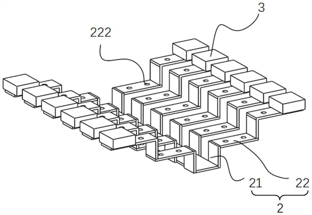
[0051] Such as Figure 1-7 As shown, the number of vibrating plates 2 connected to each side of the clamping port 131 is multiple and arranged at intervals, preferably arranged side by side at intervals, that is, there is a certain gap between the second vibrator plates 22 . The number and structure of the vibrating plates 2 located on opposite sides of the clamping opening 131 are preferably arranged symmetrically. A plurality of side-by-side vibrating plates 2 can be arranged on each side of the clamping opening 131 .
[0052] As a deformed structure, multiple parallel flapping wings 221 are formed on the second vibrator plate 22 in the form of slits, and the multiple parallel vibrating wings 221 can be equiva...
Embodiment 3
[0054] Embodiment 3 is formed on the basis of Embodiment 1 or Embodiment 2. Through the optimized design of the overall structure of the second vibrator plate in the vibration plate, the overall operating frequency of the vibration plate is reduced, and the low-frequency vibration suppression effect is improved. specifically:
[0055] Such as Figure 1-7 As shown, the first microhole 222 is opened on the second vibrator plate 22, and there are a plurality of first microholes 222. Preferably, the plurality of first microholes 222 are evenly distributed on the second vibrator plate 22. When the second vibrator When the plate 22 is provided with a plurality of flapping fins 221 , the first microholes 222 are distributed on the flapping fins 221 . The second vibrator plate 22 is provided with a first microhole 221 , which can further adjust the bending stiffness of the second vibrator plate 22 , thereby lowering the overall operating frequency of the vibrator plate.
[0056] Fur...
PUM
 Abstract
Description
Claims
Application Information
 - R&D
- Intellectual Property
- Life Sciences
- Materials
- Tech Scout
- Unparalleled Data Quality
- Higher Quality Content
- 60% Fewer Hallucinations
Browse by: Latest US Patents, China's latest patents, Technical Efficacy Thesaurus, Application Domain, Technology Topic, Popular Technical Reports.
© 2025 PatSnap. All rights reserved.Legal|Privacy policy|Modern Slavery Act Transparency Statement|Sitemap|About US| Contact US: help@patsnap.com