
Hydraulic slotting and drilling coal slag conveying and separating device

A technology of hydraulic slitting and separating device, which is applied to safety devices, drainage, earthwork drilling and other directions, can solve the problems of large discharge of coal slag and difficulty in cleaning, etc. The effect of preventing siltation at the construction site, preventing nozzle holes and abnormal gushing

Active Publication Date: 2021-05-25
CHINA COAL TECH & ENG GRP CHONGQING RES INST CO LTD
View PDF8 Cites 2 Cited by
  • Summary
  • Abstract
  • Description
  • Claims
  • Application Information

AI Technical Summary

Problems solved by technology

[0004] In view of this, in view of the problem of large amount of cinders discharged and difficult cleaning when using ultra-high pressure hydraulic slotted drilling in coal mines, the purpose of the present invention is to provide a hydraulic slotted drilling cinder transmission and separation device to realize ultra-high pressure hydraulic slotted drilling Discharge coal slag for long-distance transmission and solid-liquid separation to reduce the labor intensity of on-site staff, reduce manpower input, and improve on-site construction efficiency

Method used


Image

  • Hydraulic slotting and drilling coal slag conveying and separating device

Examples


Embodiment Construction

[0023] The embodiments of the present invention are described below through specific specific examples, and those skilled in the art can easily understand other advantages and effects of the present invention from the contents disclosed in this specification. The present invention can also be implemented or applied through other different specific embodiments, and various details in this specification can also be modified or changed based on different viewpoints and applications without departing from the spirit of the present invention. It should be noted that the drawings provided in the following embodiments are only used to illustrate the basic idea of ​​the present invention in a schematic manner, and the following embodiments and features in the embodiments can be combined with each other without conflict.

[0024] Among them, the accompanying drawings are only used for exemplary description, and represent only schematic diagrams, not physical drawings, and should not be ...


PUM


Abstract

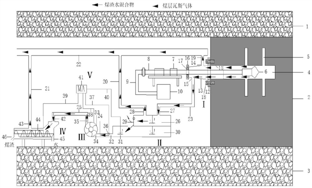
The invention belongs to the field of coal mine gas extraction drilling coal slag cleaning, and relates to a hydraulic slotting and drilling coal slag conveying and separating device. The hydraulic slotting and drilling coal slag conveying and separating device is used for separating coal slag and gas in a drill hole in the drilling and slotting process of a drill rod. The hydraulic slotting and drilling coal slag conveying and separating device comprises a drilling slag collecting device, a coal slag collecting box, a coal slag conveying pump, a coal slag separator and an automatic control system, wherein the drilling slag collecting device, the coal slag collecting box, the coal slag conveying pump and the coal slag separator are sequentially connected through a slag slurry pipe, and the automatic control system is used for controlling the coal slag conveying pump and the coal slag separator to be started and stopped; the drilling slag collecting device is arranged on the outer side of the drill rod and the end of the drill hole in a sleeving manner; the drilling slag collecting device, the coal slag collecting box and the coal slag conveying pump are all connected to a main extraction pipe through a gas extraction pipe; and a stirring impeller is arranged in the coal slag collecting box. The device can achieve automatic starting and stopping, operation is easy and convenient, the coal slag cleaning work human input cost can be effectively reduced, and the work intensity of field personnel is relieved.

Description

technical field [0001] The invention belongs to the field of coal mine gas drainage drilling coal slag cleaning, and relates to a hydraulic slit drilling coal slag transmission and separation device Background technique [0002] The proportion of high gas outburst mines in my country's coal mines is relatively large, and the construction of gas drainage boreholes inside the coal seam is the main method of gas control. At present, most coal mine construction gas drainage boreholes generally use hydraulic drilling. With the continuous development of coal mine gas control technology and equipment, hydraulic pressure relief and permeability enhancement measures have become the main means of coal mine disaster prevention and control. The ultra-high pressure hydraulic slitting technology has the advantages of strong coal breaking capacity, controllable slitting effect, and significant drilling pressure relief effect, and has been successfully popularized and applied in major mini...

Claims


Application Information

Patent Timeline
Patent Type & Authority Applications(China)
IPC IPC(8): E21B21/06E21B21/01E21F7/00E21F16/00
CPCE21B21/065E21B21/01E21F7/00E21F16/00
Inventor 张永将国林东赵旭生陆占金李成成牛心刚徐遵玉黄振飞季飞袁本庆刘永三李帅刘怀付
Owner CHINA COAL TECH & ENG GRP CHONGQING RES INST CO LTD
Learn More