
Monitoring equipment cleaning management device

A technology for managing devices and monitoring equipment, applied in combination devices, cleaning methods and utensils, cleaning methods using tools, etc., can solve the problems of blurred pictures, cameras will not be cleaned, and camera cleaning methods are inconvenient, and achieve high transparency. The effect of light, reducing the frequency of cleaning

Active Publication Date: 2021-05-25
BEIJING TELLHOW INTELLIGENT ENG CO LTD
View PDF9 Cites 0 Cited by
  • Summary
  • Abstract
  • Description
  • Claims
  • Application Information

AI Technical Summary

Problems solved by technology

Therefore, the cleaning method of the existing camera is very inconvenient, resulting in that the camera will not be cleaned for a long time, usually resulting in a relatively blurred picture when the surveillance video needs to be retrieved for evidence collection

Method used


Image

  • Monitoring equipment cleaning management device
  • Monitoring equipment cleaning management device

Examples


Embodiment Construction

[0024] The following is further described in detail through specific implementation methods:

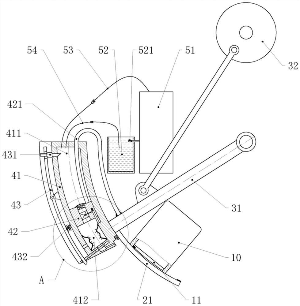
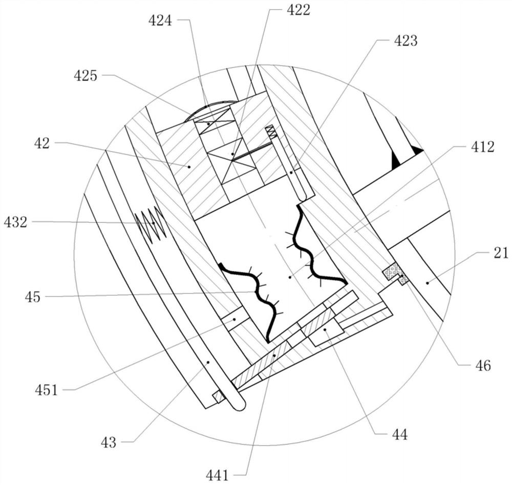
[0025] The reference signs in the drawings of the description include: camera 10, lens 11, cover 21, rocker 31, crank 32, cylinder 41, upper cavity 411, lower cavity 412, piston 42, U-shaped rod 421, exhaust valve 422, control pressure rod 423, net cover 424, exhaust one-way valve 425, control lever 43, wedge 431, compression spring 432, intake valve 44, valve core 441, elastic layer 45, through hole 451, dust strip 46 , main water tank 51, auxiliary water tank 52, float switch 521, second pipeline 53, first pipeline 54.

[0026] The embodiment is basically as attached figure 1, figure 2 Shown:

[0027] The monitoring equipment cleaning management device comprises a mounting frame, a camera 10 fixed on the mounting frame, and a cleaning management system arranged on the mounting frame. The cleaning management system includes an infrared sensor facing the same direction as the ca...


PUM


Abstract

The invention relates to monitoring equipment, and particularly discloses a monitoring equipment cleaning management device. The monitoring equipment cleaning management device comprises a mounting frame, a camera fixed to the mounting frame and a cleaning management system arranged on the mounting frame, wherein the cleaning management system comprises an infrared sensor, a shielding part, a power part and a control module; the shielding part comprises a sliding frame and a blocking cover; the blocking cover is in sliding connection with the sliding frame; the power part can drive the blocking cover to stretch out and draw back relative to the sliding frame; when the blocking cover stretches out of the sliding frame, the blocking cover shields the camera; when the blocking cover retracts back to the sliding frame, the camera is exposed; when the infrared sensor receives an infrared signal and sends out a feedback signal, the control module sends out an execution signal to the power part after receiving the feedback signal, and the blocking cover retracts into the sliding frame; and when the feedback signal is not received within 20-40 min, the control module sends out the execution signal to the power part, and the power part drives the blocking cover to stretch out of the sliding frame. Through shading of the camera, dust attached to the camera is reduced.

Description

technical field [0001] The invention relates to monitoring equipment, in particular to a monitoring equipment cleaning management device. Background technique [0002] With the development of science and technology, surveillance cameras have been more and more integrated into our lives. They are distributed in many areas such as roads, houses, and public places to ensure the safety of people's bodies and property, realize the monitoring of various areas, and play a role in security. effect. The surface of the surveillance camera will be covered with a layer of dust after long-term use. These dusts will block light, refract and reflect light, cause light scattering, make the captured image dim, and reduce the contrast. Especially the light scattering improves the clarity of image imaging. [0003] Existing camera cleaning methods usually require the camera to be removed for wiping and cleaning, or the staff utilizes a cleaning tool to directly wipe and clean the lens of the ...

Claims


Application Information

Patent Timeline
Patent Type & Authority Applications(China)
IPC IPC(8): B08B1/00B08B7/02B08B15/04B01D50/00B01D47/02H04N5/225
CPCB08B15/04B08B7/02B01D50/00B01D47/02H04N23/00B08B1/165B08B1/30
Inventor 陈军
Owner BEIJING TELLHOW INTELLIGENT ENG CO LTD
Learn More