Image distance measurement method and device, distance measurement equipment and readable storage medium
A measurement method and technology of image distance, applied in the field of image processing, can solve the problems of reading errors, time-consuming, low precision, etc.
- Summary
- Abstract
- Description
- Claims
- Application Information
AI Technical Summary
Problems solved by technology
Method used
Image

Examples
Embodiment 1
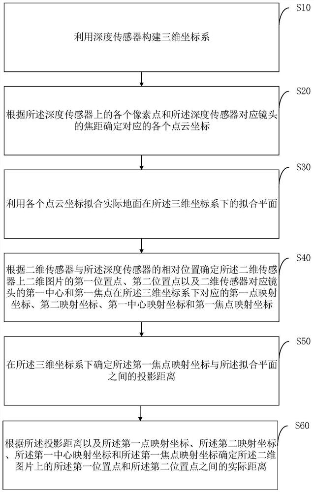
[0064] For this example, see figure 1 , showing an image distance measurement method comprising the following steps:
[0065] S10: Construct a three-dimensional coordinate system by using a depth sensor.
[0066] The depth sensor can acquire the three-dimensional information of the image, and the depth information of the image acquired by the depth sensor can be used to construct a three-dimensional coordinate system.
[0067] Exemplarily, a three-dimensional coordinate system can be established with the center of the depth sensor as the origin and the optical axis of the depth sensor as the z-axis; it can also be established with a predetermined point on the depth sensor as the origin and the optical axis of the depth sensor as the z-axis 3D coordinate system. It can be understood that different origin positions of the three-dimensional coordinate system will affect the abscissa and ordinate of the coordinate point.
[0068] S20: Determine corresponding point cloud coordin...
Embodiment 2
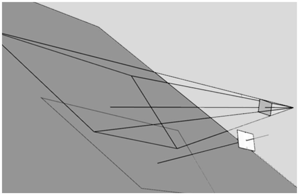
[0088] In this embodiment, a three-dimensional coordinate system is established with the center of the depth sensor as the origin and the optical axis of the depth sensor as the z-axis. The schematic diagram of the projection of the two-dimensional sensor and the depth sensor on the ground is as follows: figure 2 As shown, wherein, the relative position of the two-dimensional sensor and the depth sensor includes that the first plane of the depth sensor is parallel to the bottom edge of the second plane of the two-dimensional sensor, the normal of the first plane and the second plane The included angle between the normals of the two planes is fixed, and the center distance between the center of the depth sensor and the center of the two-dimensional sensor is fixed, and the bottom side is the side closest to the ground.
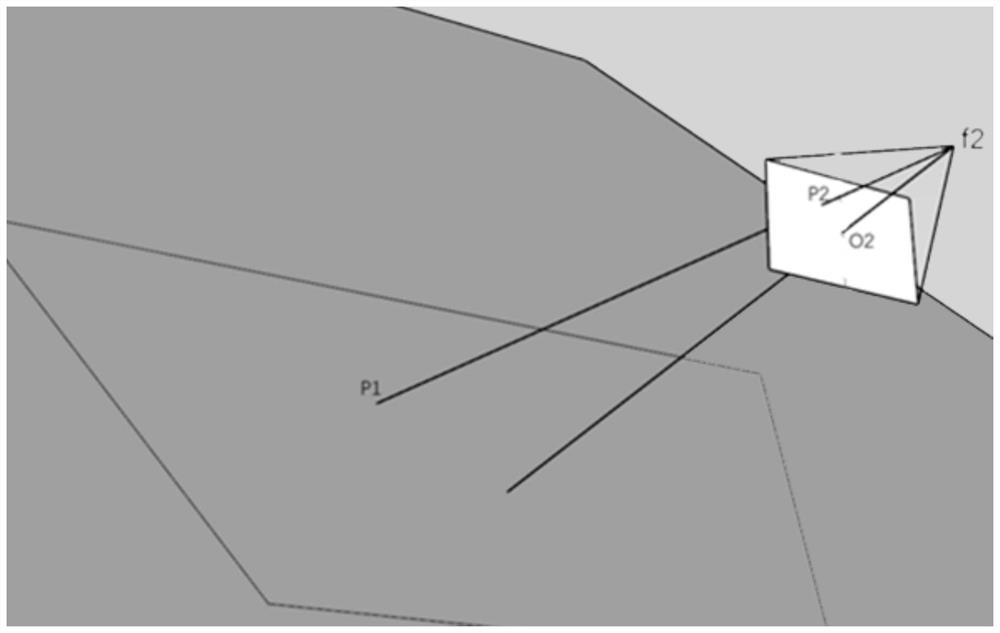
[0089] Further, the schematic diagram of the depth sensor projected on the ground is as follows image 3 shown. Take the center of the depth sensor as the o...
Embodiment 3
[0100] For this example, see Figure 6 , shows that an image distance measurement device 10 includes a three-dimensional coordinate system construction module 11, a point cloud coordinate determination module 12, a fitting plane determination module 13, a mapping coordinate determination module 14, a projected distance determination module 15 and an actual distance determination module 16 .
[0101] The three-dimensional coordinate system construction module 11 is used to construct a three-dimensional coordinate system by using the depth sensor; the point cloud coordinate determination module 12 is used to determine corresponding points according to each pixel point on the depth sensor and the focal length of the corresponding lens of the depth sensor Cloud coordinates; Fitting plane determining module 13, for utilizing each point cloud coordinates to fit the fitting plane of the actual ground under the three-dimensional coordinate system; Mapping coordinate determining module...
PUM
 Abstract
Description
Claims
Application Information
 - Generate Ideas
- Intellectual Property
- Life Sciences
- Materials
- Tech Scout
- Unparalleled Data Quality
- Higher Quality Content
- 60% Fewer Hallucinations
Browse by: Latest US Patents, China's latest patents, Technical Efficacy Thesaurus, Application Domain, Technology Topic, Popular Technical Reports.
© 2025 PatSnap. All rights reserved.Legal|Privacy policy|Modern Slavery Act Transparency Statement|Sitemap|About US| Contact US: help@patsnap.com