
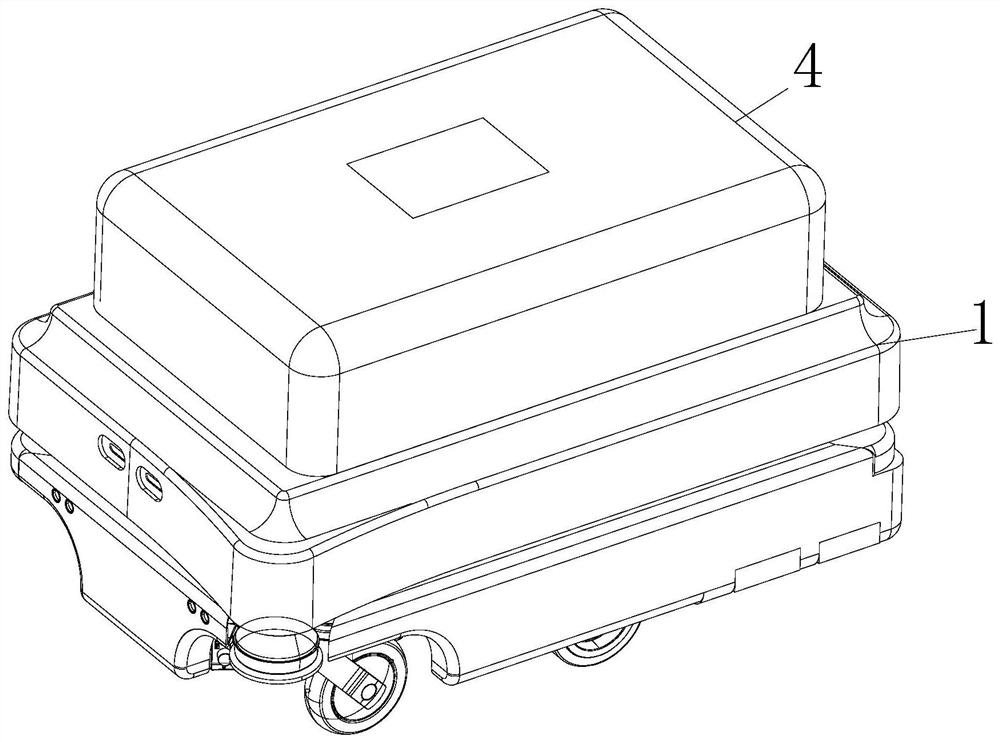
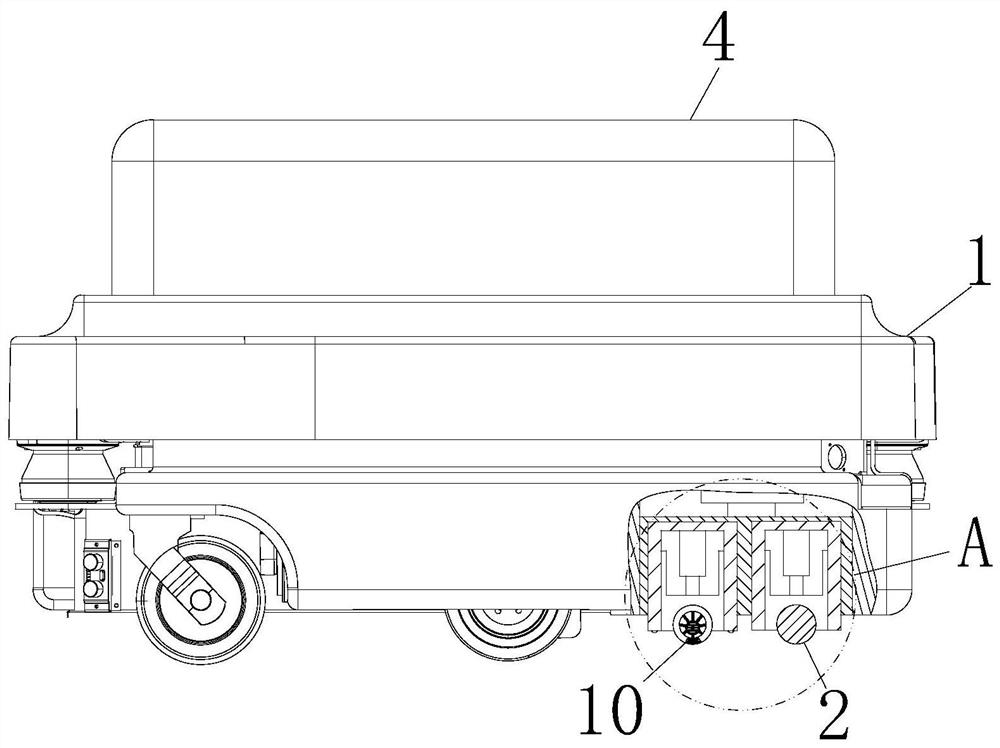
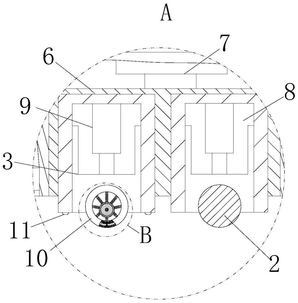
An epoxy floor construction coating machine

An epoxy floor and coating machine technology, which is applied in construction, building structure, etc., can solve the problems of difficulty in meeting the requirements of paint thickness, excessive overflow, and difficulty in controlling the amount of epoxy paint, so as to avoid uneven coating. , The effect of improving the coating quality and avoiding poor construction problems such as lack of materials

Active Publication Date: 2021-12-03
乐清市路航电气有限公司
View PDF6 Cites 0 Cited by
  • Summary
  • Abstract
  • Description
  • Claims
  • Application Information

AI Technical Summary

Problems solved by technology

[0004] However, in the prior art, many coating machines are directly used for construction to reduce manpower. The existing coating machine directly imports the paint inside the paint pot to the surface of the roller brush, or sprays it near the roller brush, and then passes the paint through the roller brush. The epoxy paint can be evenly applied to the floor surface by rolling, but the coating machine has the following problems. First, the rolling brush is directly attached to the ground and rolled, and the epoxy paint is thin and has a fixed thickness, which is difficult to meet Different paint thickness requirements; second, because the epoxy paint is directly introduced to the surrounding or surface of the roller brush, the amount of epoxy paint is difficult to control, and the export is less, which cannot meet the coating requirements. If the export is too much, it is easy to produce more The overflow of the epoxy paint is difficult to export uniformly, and it is easy to cause the problem of lack of coating material; third, due to the process of painting, there will be a small amount of dust remaining on the ground, which will also affect the coating quality and other problems

Method used


Image

  • An epoxy floor construction coating machine
  • An epoxy floor construction coating machine
  • An epoxy floor construction coating machine

Examples


Embodiment approach

[0029] As an embodiment of the present invention, the inside of the guide cavity 16 is fixedly connected with the stirring rod 17 at the axial position of the moving column 15; the inside of the stirring rod 17 is provided with a heating chamber; the inside of the heating chamber is fixedly connected There is a heating rod 18; during work, by setting the stirring rod 17 inside the guide cavity 16, the stirring of the epoxy paint 5 can be promoted on the one hand, and the internal heating rod 18 of the stirring rod 17 can convectively flow into the inside of the guide cavity 16. The epoxy paint 5 is heated to promote the softening of the epoxy paint 5, improve the fluidity of the epoxy paint 5, and reduce the flow resistance of the epoxy paint 5.

[0030] As an embodiment of the present invention, the inner surface of the cavity 14 is provided with uniformly arranged guide grooves; inside the guide grooves, guide blocks 19 are slidably connected; between the guide blocks 19 and ...


PUM


Abstract

The invention belongs to the technical field of construction equipment, and is specifically an epoxy floor construction coating machine, which includes a body, a rolling brush and an adjustment block; a paint pot is fixedly connected to the top of the body; the bottom of the body is close to the body The side position of the sliding block is slidably connected with a sliding block; the surface of the sliding block is fixedly connected with the first electric telescopic rod; the bottom of the sliding block is provided with an adjustment slot; the inside of the adjustment slot is slidingly connected with an adjustment block; the adjustment The same second electric telescopic rod is fixedly connected between the block and the groove bottom of the adjustment groove; the bottom of one of the adjustment blocks is rotatably connected with a rolling brush; the bottom of the other adjustment block is rotatably connected with a support roller; The invention effectively realizes the automatic adjustment of the coating thickness to meet the requirements of different coating thicknesses, and the support roller can initially flatten the epoxy paint, avoid uneven coating, and at the same time avoid poor construction problems such as material shortage, Improved coating quality.

Description

technical field [0001] The invention belongs to the technical field of construction equipment, in particular to an epoxy floor construction coating machine. Background technique [0002] Epoxy resin paint is a coating with epoxy resin paint as the main film-forming substance. There are many types and each has its own characteristics. According to the curing method, there are white-dry single-component, two-component and multi-component liquid epoxy coatings; Baked one-component, two-component liquid epoxy coatings; powder epoxy coatings and radiation-cured epoxy coatings, classified by coating state into solvent-based epoxy coatings, solvent-free epoxy coatings and water-based epoxy coatings. [0003] According to CN210767869U a kind of epoxy floor construction coating machine, just can realize the floor coating of large area by pulling coating machine, greatly improved the effect of coating efficiency. [0004] However, in the prior art, many coating machines are directly ...

Claims


Application Information

Patent Timeline
Patent Type & Authority Patents(China)
IPC IPC(8): E04F21/24
CPCE04F21/08Y02P70/10
Inventor 陈浩
Owner 乐清市路航电气有限公司
Learn More