Side lock for coded lock and coded lock

A combination lock and side lock technology, applied in the field of side locks and combination locks for combination locks, can solve the problems of inability to open the combination box, poor transmission and control relationship stability, complex transmission relationship, etc. Reliable, reduce the effect of transmission parts

Inactive Publication Date: 2021-05-14
刘洪
View PDF3 Cites 0 Cited by
  • Summary
  • Abstract
  • Description
  • Claims
  • Application Information

AI Technical Summary

Problems solved by technology

[0004] The purpose of the present invention is to provide a side lock and a combination lock for combination locks, so as to solve the problem that there are many transmission components and the complexity of the transmission relationship proposed in the above background technology, which not only leads to poor stability of the entire transmission and control relationship, but also tends to cause transmission failure. , and the structure of the side lock is relatively complicated, not compact enough, and not easy to assemble, which leads to high cost and high efficiency, and the user easily forgets the password during use, which leads to the inability to open the lockbox, and can only damage the side lock on the lockbox to open lockbox problem

Method used


Image

  • Side lock for coded lock and coded lock
  • Side lock for coded lock and coded lock
  • Side lock for coded lock and coded lock

Examples


Embodiment 1

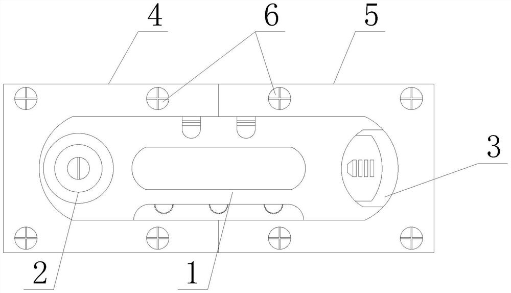
[0026] see figure 1 - Image 6 As shown, the present invention provides a technical solution: a side lock and a combination lock for a combination lock, including a combination lock main body 1, a key lock mechanism 2 is arranged at the front end of the combination lock main body 1 near the left edge, and the combination lock main body The front end surface of 1 is provided with chute 3 near the right side edge position, and the rear end of combination lock main body 1 is provided with No. Mounting plate 5, the front end surfaces of No. 1 mounting plate 4 and No. 2 mounting plate 5 are provided with bolts 6 near the four corners, and the front end surface of combination lock main body 1 is provided with coded wheel lock structure 7 near the lower edge position. The front end surface of the lock main body 1 is provided with a blocking hole 8 close to the upper edge position, the inside of the chute 3 is provided with an anti-skid plate 9, the left side of the anti-skid plate 9...

Embodiment 2

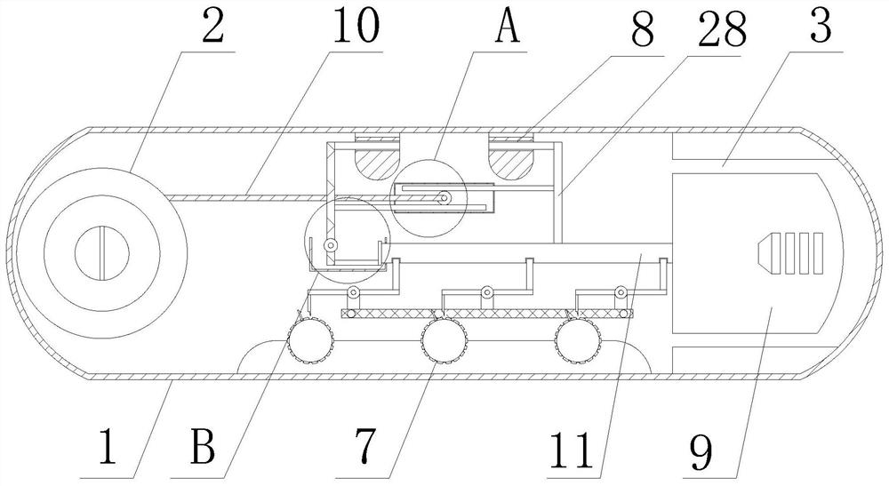
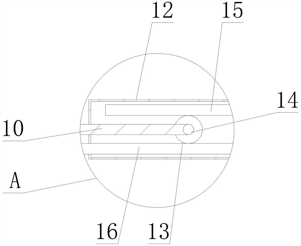
[0028] see figure 2 - image 3As shown, on the basis of Embodiment 1, a connecting rod 10 is installed on the right side of the key lock mechanism 2, and a rotating rod 14 is movably installed in the middle of the rotating gear 13, and the right side of the connecting rod 10 is connected with the rotating rod 14, and the rotation The upper end of gear 13 is equipped with No. 1 rack 15, and the lower end of rotating gear 13 is equipped with No. 2 rack 16. Rotating gear 13 drives No. 1 rack 15 and No. 2 rack 16 to move left and right in fixed frame 12, and moving rod 11 The upper end of the upper end is welded with blocking bar 28, and the right side of the No. 1 tooth bar 15 is fixed with the left side of blocking bar 28, and the left side of No. 2 tooth bar 16 is fixed with the right side of special-shaped bar 20, wherein, by controlling the key lock The mechanism 2 can drive the connecting rod 10, make it drive the rotating rod 14 to rotate, and make the rotating rod 14 dri...

Embodiment 3

[0030] see Figure 5 - Image 6 As shown, on the basis of Embodiment 1 and Embodiment 2, the four corners of the No. 1 mounting plate 4 and the No. 2 mounting plate 5 are provided with threaded holes 22, and the middle position of the upper end surface of the connecting plate 21 is provided with a No. long slot 26, the upper end surface of connecting plate 21 and the front and back side of No. 1 long slot 26 are provided with No. 2 long slot 27, and long block 24 is installed in No. In the No. 2 long slot 26, the No. 2 mounting plate 5 fits with the storage slot 23, wherein, by pushing the No. 2 mounting plate 5, and cooperating with the No. 2 long slot 27 through the limit slider 25, the No. 2 mounting plate 5 is stored in the same direction. Move in the slot 23, and then by pushing the No. 1 mounting plate 4, it moves in the No. 1 long slot 26 through the long block 24, so that the No. 1 mounting plate 4 can move to the middle of the connecting plate 21, and then can It is...


PUM


Abstract

The invention discloses a side lock for a coded lock and the coded lock, and relates to the technical field of locks. The side lock comprises a coded lock body, wherein a key lock mechanism is arranged at the position, close to the left side edge, of the front end of the coded lock body, a sliding groove is formed in the position, close to the right side edge, of the surface of the front end of the coded lock body, a first mounting plate is arranged at the rear end of the coded lock body, and a second mounting plate is arranged at the rear end of the coded lock body and located on the right side of the first mounting plate. According to the side lock for the coded lock and the coded lock, transmission parts of the side lock can be reduced, the transmission relation is simplified, the transmission control performance is more stable and reliable, the structure of the side lock is simpler and more compact, the side lock is convenient to assemble, a code case can be opened through a key when a password wheel lock is forgotten, the situation that the code case cannot be used is prevented, rapid combination of the side lock and the code case can be facilitated, the side lock and the code case can be rapidly assembled and disassembled, and the side lock can be conveniently replaced.

Description

technical field [0001] The invention relates to the technical field of locks, in particular to a side lock and a combination lock for a combination lock. Background technique [0002] Combination lock is a kind of lock. A series of numbers or symbols are used to open it. Text combination lock can be divided into: mechanical combination lock, digital combination lock, etc. The password of combination lock is usually just an arrangement rather than a real combination. , some combination locks only use a turntable to rotate several discs or cams in the lock, and some combination locks turn a set of dials engraved with numbers to directly drive the mechanism inside the lock. [0003] Combination locks on the market use side locks and combination locks. There are many transmission parts and the complexity of the transmission relationship not only leads to poor stability of the entire transmission and control relationship, but also prone to transmission failure, and makes the stru...

Claims


Application Information

Patent Timeline
Patent Type & Authority Applications(China)
IPC IPC(8): E05B15/00E05B37/00E05B37/12
CPCE05B15/00E05B37/0034E05B37/12
Inventor 刘洪
Owner 刘洪
Why Eureka
Try Eureka