Massager driving device

A driving device and massager technology, applied in vibration massage, massage auxiliary products, physical therapy and other directions, can solve the problems of insufficient bearing capacity and uneven force of parallel double chutes, so as to prolong the life, avoid skew, and ensure the The effect of force stability

Pending Publication Date: 2021-05-14
温州普乔工艺品有限公司
View PDF0 Cites 0 Cited by
  • Summary
  • Abstract
  • Description
  • Claims
  • Application Information

AI Technical Summary

Problems solved by technology

[0006] In the above structure, the first chute and the second chute are arranged on the outer wall of the outer cylindrical cam, and the reciprocating strokes of the two are arranged staggered by 180 degrees in the circumferential direction of the outer wall of the outer cylindrical cam, so that the sliding pin can move in the circumferential direction of the rotary sleeve. The top is set at 180 degrees, and is respectively adapted to slide with the first chute and the second chute, which ensures the stress stability of the telescopic sleeve during reciprocating motion and prevents the telescopic sleeve from being skewed. The first chute and the second chute The intersection points between the two slots are located in the middle of each other’s stroke, effectively avoiding the situation where the first chute and the second chute bear the largest reciprocating reverse load at the 6 o’clock and 12 o’clock positions of the cam section on the outer cylindrical surface. In the area, when the outer cylindrical surface cam drives the telescopic sleeve to enter the middle position of the stroke of the reverse movement, skillfully use the auxiliary guidance of the deeper first chute and the sliding pin to continue to push the telescopic sleeve to slide, so that it is compatible with the second chute. When the matching sliding pin passes through the intersecting part of the second chute and the first chute and loses the guiding support with the second chute, it can smoothly cross the intersection point, so that the second chute can re-fit and slide with the sliding pin, which solves the problem of single The bearing capacity of the chute is not enough, and the parallel double chute is unevenly stressed, which ensures the stability and reliability of the work and prolongs the life of the massager driving device

Method used


Image

  • Massager driving device
  • Massager driving device
  • Massager driving device

Examples


Embodiment Construction

[0026] The specific implementation manners of the present invention will be further described in detail below in conjunction with the accompanying drawings and embodiments. The following examples are used to illustrate the present invention, but are not intended to limit the scope of the present invention.

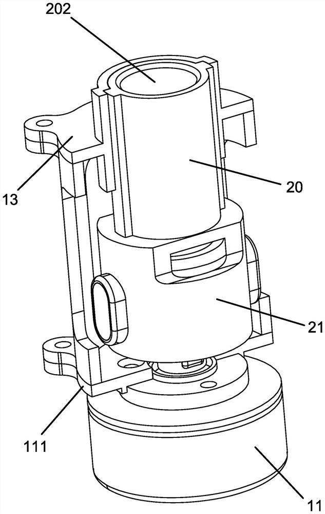
[0027] refer to Figure 1 to Figure 5 ,like Figure 1 to Figure 5 The shown driving device for a massager comprises an outer frame 10, one end of the outer frame 10 is provided with a drive motor 11, the motor shaft of the drive motor 11 is provided with an outer cylindrical surface cam 12, and the other end of the outer frame 10 is A sliding hole 101 is provided, and a telescopic sleeve 20 adapted to the sliding hole 101 is provided inside the outer frame 10. A rotary sleeve 21 is provided on the end of the telescopic sleeve 20 facing the drive motor 11, and the outer cylindrical surface cam 12 is located on In the rotary sleeve 21; the outer wall of the rotary sleeve 2...


PUM


Abstract

A massager driving device is provided and comprises an outer frame, wherein a driving motor is arranged at one end of the outer frame, an outer cylindrical surface cam is arranged on the driving motor, a sliding hole is formed in the other end of the outer frame, a telescopic sleeve is arranged in the outer frame, a rotary sleeve is arranged at one end of the telescopic sleeve, and the outer cylindrical surface cam is located in the rotary sleeve; the outer wall of the rotary sleeve is provided with two sliding pin mounting parts which are arranged in the circumferential direction of the rotary sleeve at an interval of 180 degrees, and sliding pins extending into the rotary sleeve are mounted on the sliding pin mounting parts; a first sliding groove and a second sliding groove are formed in the outer wall of the outer cylindrical surface cam, the strokes of the first and second sliding grooves are spaced by 180 degrees in the circumferential direction of the outer wall of the outer cylindrical surface cam, the depth of the first sliding groove is larger than that of the second sliding groove, the sliding pins are matched with the first and second sliding grooves respectively, and the length of the sliding pin of the first sliding groove penetrating into the inner wall of the rotary sleeve is larger than that of the second sliding groove. The device has the advantages of strong bearing capacity, stable work and short axial dimension.

Description

technical field [0001] The invention relates to the field of massagers, in particular to a driving device for a massager. Background technique [0002] There are many types of existing massagers, among which the fascia gun is an essential equipment for anti-loosening massage, and its driving methods are also different. The general fascia gun uses a motor to drive the crankshaft, and the crankshaft drives the connecting rod to realize the fascia loosening. The expansion and contraction of the gun massage head makes the drive mechanism larger in the longitudinal direction, which is not conducive to the miniaturization of the product; [0003] According to the above problems, designers have continuously optimized and improved, such as changing the traditional brushed motor to a brushless motor, greatly shortening the axial size of the motor, or changing the crankshaft and crank structure to the form of end face cam and pin head cooperation to achieve miniaturization , but the ...

Claims


Application Information

Patent Timeline
Patent Type & Authority Applications(China)
IPC IPC(8): A61H23/02
CPCA61H23/02A61H2201/0165A61H2201/1418
Inventor 刘涛黄星泉
Owner 温州普乔工艺品有限公司
Why Eureka
Try Eureka