Preparation equipment of non-Newtonian fluid modified starch for interesting games
A non-Newtonian fluid, modified starch technology, applied in mixer accessories, dissolving, mixers, etc., can solve the problems of long time, low preparation efficiency, and large effort.
- Summary
- Abstract
- Description
- Claims
- Application Information
AI Technical Summary
Problems solved by technology
Method used
Image
Examples
Embodiment 1
[0061] A non-Newtonian fluid modified starch preparation equipment for fun games, such as figure 1 As shown, it includes a bottom plate 1, a workbench 2, a motor 3, a stirring mechanism 4 and a water outlet mechanism 5. A workbench 2 is installed on the top of the bottom plate 1, and a motor 3 is fixed on the front right of the top of the workbench 2 by bolts. 2 The front side is penetratingly provided with a stirring mechanism 4, which is connected to the output shaft of the motor 3, and a water outlet mechanism 5 is installed on the rear side of the top of the workbench 2.
[0062]When a worker needs to prepare modified starch, the worker needs to pour an appropriate amount of water into the water outlet mechanism 5, and then the worker needs to pour an appropriate amount of starch into the mixing mechanism 4, and when the starch is in the mixing mechanism 4, the worker needs to open the water outlet mechanism 5. The water in the water outlet mechanism 5 will flow into the s...
Embodiment 2
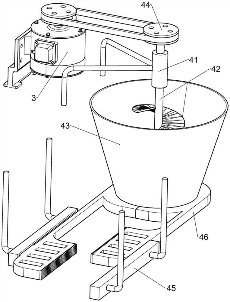
[0064] In a preferred embodiment of the present invention, as figure 2 As shown, the stirring mechanism 4 includes a first rotating sleeve 41, a stirring assembly 42, a mixing bucket 43, a first transmission assembly 44, a first guide sleeve 45 and a closing plate 46, and the front side of the top of the workbench 2 is fixedly connected with a first rotating sleeve. Sleeve 41, the first rotating sleeve 41 is provided with agitating assembly 42 in rotation type, the middle part of the front side of workbench 2 is welded with agitating barrel 43 through-type, and agitating assembly 42 is in contact with the inner wall of agitating barrel 43, and the top of agitating assembly 42 is in contact with the motor 3 A first transmission assembly 44 is connected between the tops of the output shafts, and a first guide sleeve 45 is symmetrically arranged on the rear side of the bottom of the workbench 2, and a closing plate 46 is slidingly provided in the left and right first guiding slee...
Embodiment 3
[0067] In a preferred embodiment of the present invention, as figure 1 and Figure 3-Figure 8 As shown, the water outlet mechanism 5 includes a water tank 51, a valve assembly 52 and a water outlet assembly 53. A water tank 51 is placed on the rear side of the top of the workbench 2. A valve assembly 52 is provided on the left side of the top rear side of the workbench 2. The front side of the water tank 51 The lower part is penetratingly provided with a water outlet assembly 53 , the front end of the water outlet assembly 53 is located above the mixing bucket 43 , and the valve assembly 52 is in contact with the water outlet assembly 53 .
[0068] The process of workers manually pouring water into the mixing tank 43 is complicated, so the workers need to pour an appropriate amount of water into the water tank 51 first, and the water in the water tank 51 will flow into the mixing tank 43 through the water outlet assembly 53. When the worker temporarily When it is not necessar...
PUM
 Abstract
Description
Claims
Application Information
 - Generate Ideas
- Intellectual Property
- Life Sciences
- Materials
- Tech Scout
- Unparalleled Data Quality
- Higher Quality Content
- 60% Fewer Hallucinations
Browse by: Latest US Patents, China's latest patents, Technical Efficacy Thesaurus, Application Domain, Technology Topic, Popular Technical Reports.
© 2025 PatSnap. All rights reserved.Legal|Privacy policy|Modern Slavery Act Transparency Statement|Sitemap|About US| Contact US: help@patsnap.com


