
Temperature control type hydraulic cooling system

A cooling system and temperature-controlled technology, which is applied in the field of hydraulic cooling systems, can solve the problems that the oil temperature cannot be adjusted in real time, the flow of oil in the circuit cannot be adjusted, and the temperature adjustment is not timely and accurate, etc.

Pending Publication Date: 2021-05-07
SHANGHAI TIANDI MINING EQUIP TECH CO LTD +2
View PDF0 Cites 0 Cited by
  • Summary
  • Abstract
  • Description
  • Claims
  • Application Information

AI Technical Summary

Problems solved by technology

The disadvantage of this cooling system is that the oil flow in the circuit cannot be adjusted, and the oil temperature in the system cannot be adjusted in real time, so the temperature adjustment is not timely and accurate enough.

Method used


Image

  • Temperature control type hydraulic cooling system
  • Temperature control type hydraulic cooling system
  • Temperature control type hydraulic cooling system

Examples


Embodiment Construction

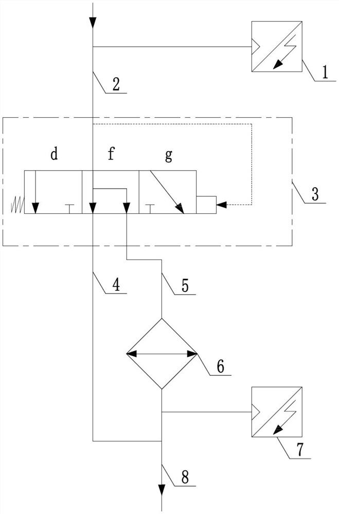
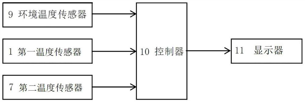
[0023] The invention discloses a temperature-controlled hydraulic cooling system, which is used to regulate the oil temperature of the hydraulic system, such as figure 1 , 2 As shown in . A branch oil passage 4 and a second branch oil passage 5 are connected to an oil return pipeline 8 . The radiator is arranged on the second branch oil circuit.

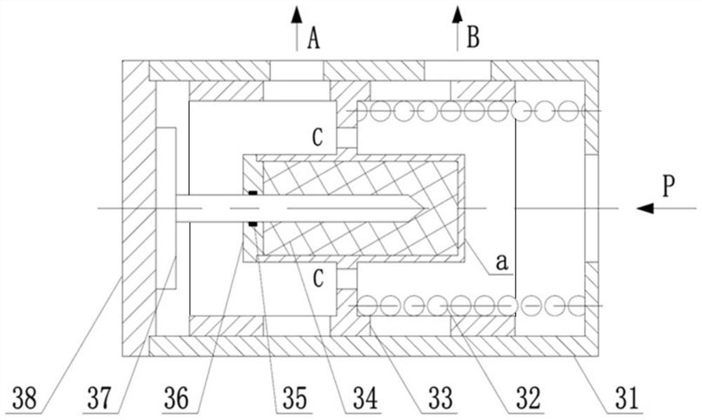
[0024] The temperature control valve includes a valve sleeve, a heat-sensitive material 34 located in the inner cavity of the valve sleeve, a spring 32 and a valve core 33 slidingly fitted with the valve sleeve. The two ends of the spring are respectively fixedly connected to the valve sleeve and the valve core, and the deformation direction of the spring is parallel to the sliding direction of the valve core. The heat-sensitive material is affected by the temperature change of the oil in the inner cavity of the valve sleeve to cause thermal expansion and contraction deformation. The heat-sensitive material and the spring work tog...


PUM


Abstract

The invention relates to a temperature control type hydraulic cooling system which comprises a temperature control valve and a radiator. A valve inlet of the temperature control valve is connected with an oil inlet pipeline, a first valve outlet and a second valve outlet of the temperature control valve are connected with an oil return pipeline through a first branch oil way and a second branch oil way respectively, and the radiator is arranged on the second branch oil way. The temperature control valve comprises a valve sleeve, a heat-sensitive material located in an inner cavity of the valve sleeve, a spring and a valve element in sliding fit with the valve sleeve. The heat-sensitive material generates heat expansion and cold contraction deformation under the influence of the temperature change of oil in the inner cavity of the valve sleeve, the heat-sensitive material and the spring jointly act to drive a valve element to slide in a reciprocating mode, the on-off state and the opening degree of the first valve outlet and the second valve outlet are changed, when the valve element is located in a middle working section, the first valve outlet, the second valve outlet and the valve inlet are communicated, the opening degree of the first valve outlet is decreased along with rising of the oil temperature, and the opening degree of the second valve outlet is increased along with rising of the oil temperature. According to the invention, the oil temperature of the hydraulic system can be spontaneously adjusted in real time.

Description

technical field [0001] The invention relates to a hydraulic cooling system, especially a system capable of real-time temperature adjustment. Background technique [0002] The cooling system is an indispensable part of the hydraulic system of construction machinery, which can provide suitable oil temperature for the hydraulic system and ensure the long-term and efficient operation of the hydraulic system. At present, the cooling system in the hydraulic system of construction machinery is basically pressure-controlled, that is, the one-way circuit leading to the radiator or oil tank is opened by oil pressure. The disadvantage of this cooling system is that the oil flow in the circuit cannot be regulated, and the temperature of the oil in the system cannot be adjusted in real time, so the temperature adjustment is not timely and accurate enough. Contents of the invention [0003] The purpose of the present invention is to provide a temperature-controlled hydraulic cooling sy...

Claims


Application Information

Patent Timeline
Patent Type & Authority Applications(China)
IPC IPC(8): F15B21/0423F15B21/042F15B19/00
CPCF15B19/005F15B21/042F15B21/0423
Inventor 闫茂春叶旺盛郭强高奔高志明董程林潘峰冯晓迪汪贝吴靖宇
Owner SHANGHAI TIANDI MINING EQUIP TECH CO LTD
Learn More