Antenna panel, vortex beam antenna and working method thereof
An antenna panel and vortex technology, applied in the direction of antenna, antenna array, antenna grounding switch structure connection, etc., can solve the problems of limited operating bandwidth and strong frequency dependence, achieve easy miniaturization and integration, and achieve miniaturization and integrated effects
- Summary
- Abstract
- Description
- Claims
- Application Information
AI Technical Summary
Problems solved by technology
Method used
Image

Examples
Embodiment 1
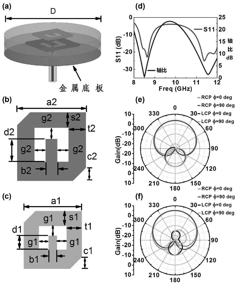
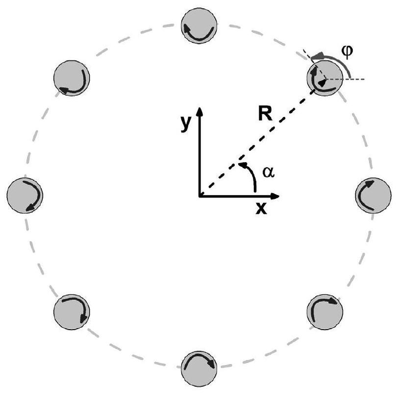
[0068] Embodiment 1 of the present invention discloses an antenna panel, the structure of which is as follows image 3 , Figure 4 As shown in (a), the antenna panel contains at least one antenna array, and the antenna array includes a plurality of antenna units uniformly distributed along the circumference, and the orientation angles of the plurality of antenna units change sequentially with the change of the direction angle of the antenna units.
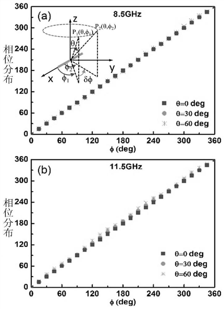
[0069] Compared with the prior art, the antenna panel provided by the present invention can realize broadband control of the radiation phase of the circularly polarized electric field in three-dimensional space through the geometric rotation of the antenna elements in the antenna panel. That is, the phase shifting function can be realized by using the rotation of the antenna unit itself, and the realization of the phase shifting function has nothing to do with the structure of the antenna unit itself. Specifically, the antenna pan...
Embodiment 2
[0075] Embodiment 2 of the present invention discloses a vortex beam antenna, such as Figure 4As shown, it includes any antenna panel above, and a power divider arranged under the antenna panel, the number of layers of the power divider is consistent with the number of antenna arrays, and is connected to the antenna array in one-to-one correspondence, for Realize power distribution. Since the above-mentioned antenna panel can realize the phase-shifting function, the rear end of the vortex beam antenna provided in this implementation no longer needs to be phase-shifted, thereby simplifying the original phase-shifting feed network into a simple power splitter, which overcomes the The shortcoming of narrow-band operation caused by the frequency-dependent characteristics of the phase-shifted feed network is eliminated, and the working bandwidth of the vortex beam antenna in the present invention is expanded.
[0076] Preferably, the multiple output ports of the power splitter ar...
Embodiment 3
[0078] In Embodiment 3 of the present invention, a specific three-mode vortex beam antenna size design method is given, such as Figure 4 As shown: the antenna array on the antenna panel is distributed in inner and outer circles; the inner circle is provided with two antenna arrays arranged in a staggered manner, and the corresponding orbital angular momentum modes are respectively l=+1 and l=-1; The outer ring is provided with an antenna array, and the corresponding orbital angular momentum mode is l=-2. Among them, the initial angle of the antenna element corresponding to the orbital angular momentum mode l=+1 is The initial angle of the antenna element corresponding to the orbital angular momentum mode l=-1 is The initial angle of the antenna element corresponding to the orbital angular momentum mode l=-2 is Exemplarily, in this embodiment, each antenna array in the inner ring includes 8 antenna elements, and the array in the outer ring includes 16 antenna arrays.
[...
PUM
| Property | Measurement | Unit |
|---|---|---|
| Thickness | aaaaa | aaaaa |
| Thickness | aaaaa | aaaaa |
Abstract
Description
Claims
Application Information
 - R&D
- Intellectual Property
- Life Sciences
- Materials
- Tech Scout
- Unparalleled Data Quality
- Higher Quality Content
- 60% Fewer Hallucinations
Browse by: Latest US Patents, China's latest patents, Technical Efficacy Thesaurus, Application Domain, Technology Topic, Popular Technical Reports.
© 2025 PatSnap. All rights reserved.Legal|Privacy policy|Modern Slavery Act Transparency Statement|Sitemap|About US| Contact US: help@patsnap.com