Ultrasonic scalpel with variable scalpel bar connection mode

A connection method, ultrasonic knife technology, applied in medical science, surgery, etc., can solve problems such as knife bar resonance, inability to treat patients, and knife bar breakage.

Active Publication Date: 2021-05-04
SUZHOU FRANKENMAN MEDICAL EQUIP
View PDF5 Cites 1 Cited by
  • Summary
  • Abstract
  • Description
  • Claims
  • Application Information

AI Technical Summary

Problems solved by technology

[0004] The purpose of the present invention is: in order to solve the problem that the cutter body and the cutter bar of the ultrasonic knife in the prior art are generally disassembled, which is convenient for access and storage, the connection method is generally installed by thread, and when the thread is installed, in order to install it tightly, it needs to be rotated vigorously Install the knife bar to realize the installation, but if the force is too large during the installation process, the knife bar may break, and if the force is too small, the installation may not be tight, which will easily affect the work of the ultrasonic scalpel during the operation. At the same time, the existing The blade angle of the ultrasonic scalpel cannot be adjusted, which may cause some inconvenience when people use it, and it is impossible to treat patients well according to the actual environment. At the same time, the blade of the ultrasonic scalpel will resonate during use. The problem of damaging the stability of the knife bar and affecting the treatment, and a kind of ultrasonic knife with variable connection mode of the knife bar is proposed

Method used


Image

  • Ultrasonic scalpel with variable scalpel bar connection mode
  • Ultrasonic scalpel with variable scalpel bar connection mode
  • Ultrasonic scalpel with variable scalpel bar connection mode

Examples


Embodiment Construction

[0041] The following will clearly and completely describe the technical solutions in the embodiments of the present invention with reference to the accompanying drawings in the embodiments of the present invention. Obviously, the described embodiments are only some, not all, embodiments of the present invention. Based on the embodiments of the present invention, all other embodiments obtained by persons of ordinary skill in the art without creative efforts fall within the protection scope of the present invention.

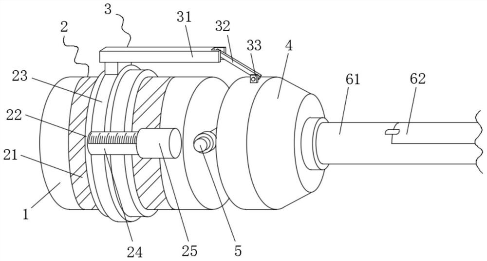
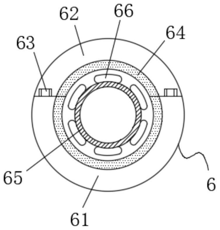
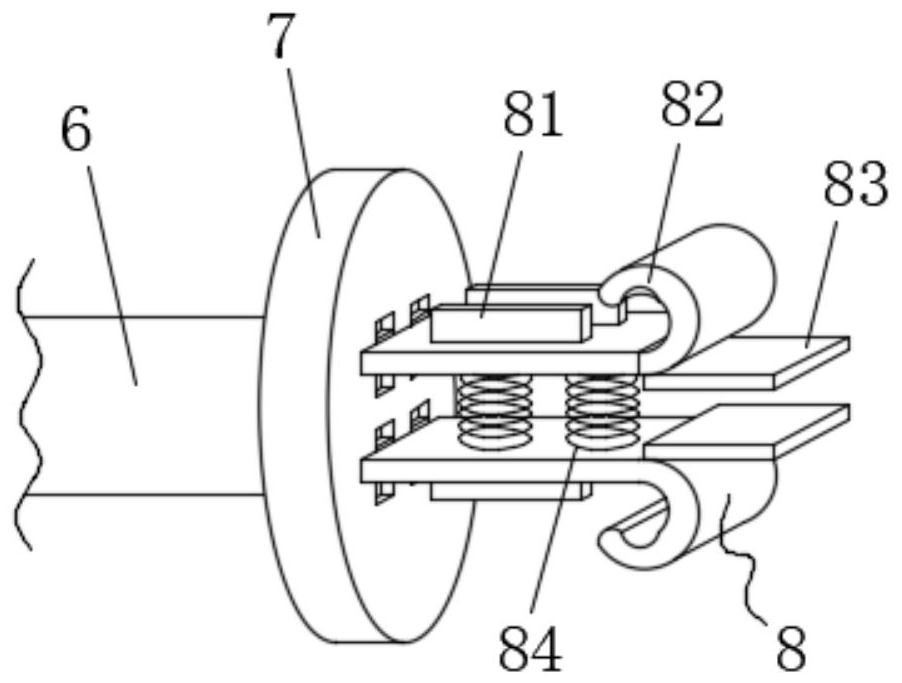
[0042] see Figure 1-8 , the present invention provides a technical solution: an ultrasonic knife with a variable connection mode of the knife bar, including an ultrasonic knife body 1, an adjustment mechanism 2 is arranged on the outside of the ultrasonic knife body 1, and one end of the adjustment mechanism 2 is connected to a push mechanism 3 One end is fixedly connected, the other end of the pushing mechanism 3 is fixedly connected to the upper surface of the f...


PUM


Abstract

The invention discloses an ultrasonic scalpel with a variable scalpel bar connection mode, and belongs to the technical field of ultrasonic scalpels. The ultrasonic scalpel comprises an ultrasonic scalpel body, wherein an adjusting mechanism is arranged on the outer side of the ultrasonic scalpel body, one end of the adjusting mechanism is fixedly connected with one end of a pushing mechanism, and the other end of the pushing mechanism is fixedly connected to the upper surface of a fixing shell. According to the ultrasonic scalpel, a mounting mechanism is arranged, when arc-shaped plates are pushed to move towards the position between two stop blocks under the action of the arc-shaped plates, under the action of arc surfaces, the two arc-shaped plates get close to each other and move to the position between the two stop blocks when being extruded, at the moment, two stop plates penetrate through the stop blocks to move into the fixing shell, sliding plates can be clamped into plate grooves at the moment, and the scalpel bar is limited and cannot shake front and back under the actions of the sliding plates and the plate grooves; and by arranging first springs, when the arc-shaped plates are not extruded any more, the first springs open two positioning plates through the elasticity of the first springs, and at the moment, the sliding plates can move and are smoothly clamped into the plate grooves.

Description

technical field [0001] The invention belongs to the technical field of ultrasonic scalpels, and in particular relates to an ultrasonic scalpel with a variable connection mode of a cutter bar. Background technique [0002] Ultrasonic scalpel is a beauty technology developed on the basis of ultrasound, which can release a high-intensity energy-concentrated ultrasound, and use the physical characteristics of ultrasound in biological tissues such as directionality, penetration, and focusability to penetrate the external energy ultrasound into normal skin. The tissue is precisely focused on the beauty treatment area in the body, and a thermal coagulation point of 65-70°C is generated instantly within 0.5s, so that the tissue cells in the target area immediately produce a protein coagulation reaction, and a pulling force is generated around the coagulation point to immediately show tightening and lifting Effect. The effect of ultrasonic scalpel usually lasts for 2 to 3 years. Th...

Claims


Application Information

Patent Timeline
IPC IPC(8): A61B17/32
CPCA61B17/320068A61B2017/320074
Inventor 周铁君孙木此
Owner SUZHOU FRANKENMAN MEDICAL EQUIP
Why Eureka
Try Eureka