
Floor treatment machine

A floor and machine technology that is used in floor treatment machines to solve problems such as operator fatigue, not very suitable for straight line movements, and it is difficult for the machine to make sharp turns to get around corners or obstacles.

Active Publication Date: 2021-04-30
NUMATIC INTERNATIONAL LIMITED
View PDF12 Cites 0 Cited by
  • Summary
  • Abstract
  • Description
  • Claims
  • Application Information

AI Technical Summary

Problems solved by technology

This is due to the lack of guiding constraints provided by the rotating work head and the dual pivot handle, which allow the user to easily sweep side to side along an arc, but are less suitable for the methodical straight line movement of the machine over the surface to be cleaned
Also, these machines are difficult to turn sharply around corners or obstacles
The labor of controlling the machine can tire the operator and limit productivity

Method used


Image

  • Floor treatment machine
  • Floor treatment machine
  • Floor treatment machine

Examples


Embodiment Construction

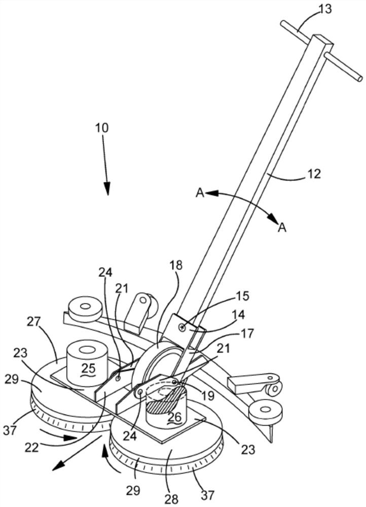
[0024] exist figure 1 In the figure, a floor scrubbing dryer according to the present invention is shown generally at 10 . The machine comprises a handle portion 12 of elongated rectangular section. The handle portion 12 includes a top end region and a bottom end region. A handle 13 is mounted transversely to the top end region of the handle portion 12 through a hole. A control unit (not shown) is also provided at the tip area. During use, the user walks behind the machine and uses the handle 13 to guide it onto the floor surface to be cleaned.

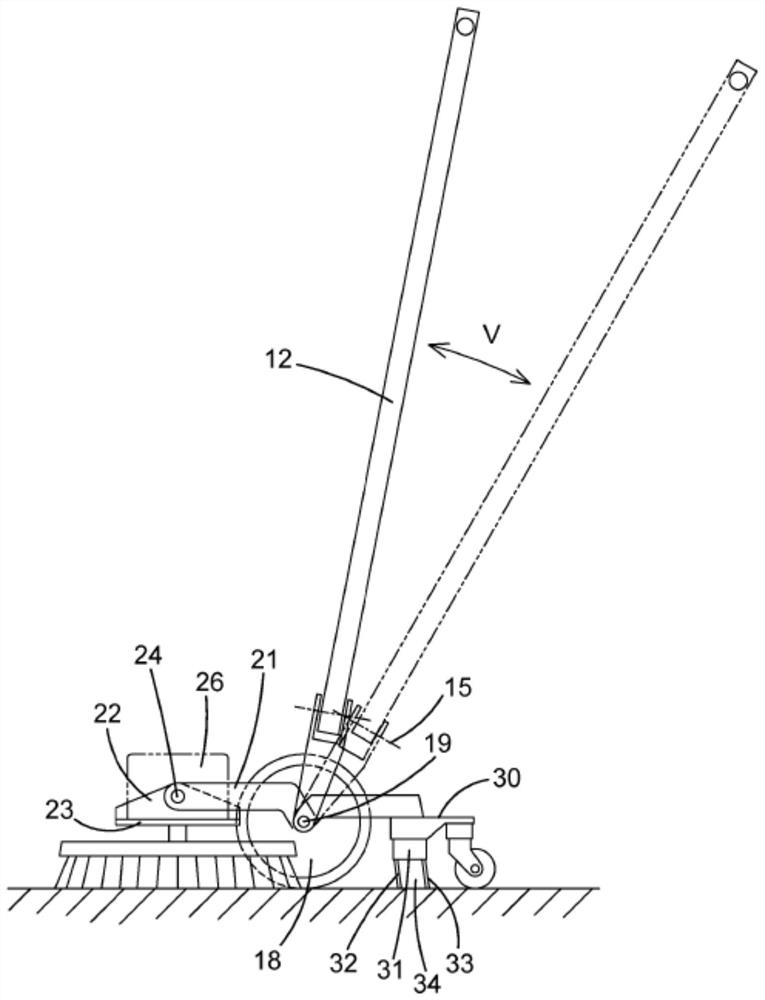
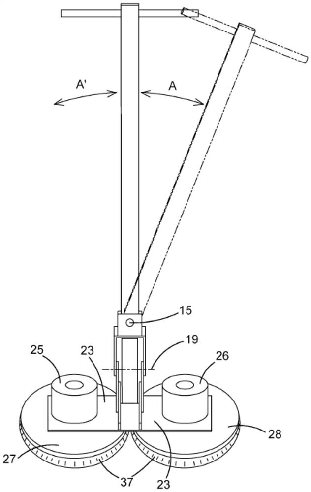
[0025] The bottom end region of the handle portion 12 is pivotally attached between upstanding ears of a U-section mounting bracket 14 . The pivot is oriented forward and backward so that the handle portion is about the pivot axis 15 relative to the bracket 14 (eg image 3 Shown by arrows A, A') can be rotated side to side. This axis 15 is substantially perpendicular to the length of the handle part 2 and allows lateral side-to-...


PUM


Abstract

The present invention relates to the field of floor treatment machines for scrubbing, polishing, sanding or burnishing floors, and in particular machines in which one or more driven rotatable work heads (such as scrubbing brushes) are provided for agitating the floor surface. In one aspect there is provided a walk-behind floor treatment machine comprising: a base portion provided with and supported by at least one rotatable work head for treating the floor, a handle portion for steering or guiding the machine along a working direction of travel and adapted to be pivotable with respect to the base portion, drive means for rotating the work head with respect to the base portion, floor-engaging wheel means for supporting the handle portion, the wheel means having a substantially transverse axis of rotation so as to permit travel in the working direction, the wheel means being coupled to the base portion by a linkage which permits vertical travel of the base portion and associated work head or heads with respect to the wheel means, but which provides transverse constraint to limit or prevent yawing of the base portion with respect to the wheel means, wherein a lower region of the handle portion is pivotably connected to the wheel means via an articulated joint, the arrangement being such that the handle portion may be manipulated to act on the wheel means so as to yaw steer the wheel means about a yaw axis defined by the floor-engaging contact of the wheel means, the yawing of the wheel means causing the base portion to yaw in response to yaw steering. The wheel means may comprise a wheel, roller or ball, preferably a single wheel, roller or ball, disposed at a lower region of the handle portion. The wheel means preferably has a fixed transverse axis of rotation.

Description

technical field [0001] The present invention relates to the field of floor treatment machines for scrubbing, polishing, sanding or calendering floors. In these machines, one or more driven rotatable working heads (such as scrubbing brushes) are provided to beat the floor surface. In particular, the present invention relates to a walk-behind machine provided with a handle for steering and guiding the machine as it travels on a floor surface. Background technique [0002] EP2832277 (i-mop GmbH) discloses a walk-behind wet floor scrubber with two side-by-side working heads each comprising a disc-shaped floor brush. There is a rear scraper and associated suction drive and reservoir for collecting liquid from the floor surface. The brushes support the weight of the machine and counter-rotate to provide propulsion. The suction drive is arranged on the handle part of the machine together with the washer water container for feeding the washer fluid dispenser. The handle has dual...

Claims


Application Information

Patent Timeline
IPC IPC(8): A47L11/08A47L11/26A47L11/40B24B7/18
CPCA47L11/08A47L11/26A47L11/4072A47L11/4075A47L11/4091B24B7/186
Inventor 西蒙·威尔特
Owner NUMATIC INTERNATIONAL LIMITED
Learn More