
Laminating machine and laminating method

A laminating machine and laminating technology, applied in the direction of conveyor objects, optics, instruments, etc., can solve the problems of low efficiency, unfavorable lamination, low production efficiency, etc.

Active Publication Date: 2021-04-30
东莞市鼎力自动化科技有限公司
View PDF11 Cites 9 Cited by
  • Summary
  • Abstract
  • Description
  • Claims
  • Application Information

AI Technical Summary

Problems solved by technology

[0003] In the existing laminating machines for wearable watches, most of the loading and unloading processes for materials such as wearable display modules, OCA optical adhesives, and wearable glass cover plates are still manually operated, which is not only labor-intensive but also production-intensive. low efficiency
At the same time, most of the cleaning and film tearing process of the material still needs to be done manually; manual tearing of the film needs to be done carefully, which is troublesome, inefficient, wasteful of manpower, material and financial resources, and the quality of the obtained products is not the same. During the filming process, the glass cover will be damaged or impurities such as dust will easily be generated on the glass cover. In addition, the traditional cleaning of the glass cover after tearing off the film is often done by manual cleaning, which is inefficient and the wiping effect is not good, which is not conducive to Late fitting

Method used


Image

  • Laminating machine and laminating method
  • Laminating machine and laminating method
  • Laminating machine and laminating method

Examples


Embodiment Construction

[0054] The technical solutions in the embodiments of the present invention will be clearly and completely described below in conjunction with the drawings in the present invention. Apparently, the described embodiments are only some of the embodiments of the present invention, not all of them. Based on the embodiments of the present invention, all other embodiments obtained by persons of ordinary skill in the art without making creative efforts belong to the protection scope of the present invention.

[0055] It should be noted that the terms "first" and "second" in the description and claims of the present application and the above drawings are used to distinguish similar objects, but not necessarily used to describe a specific sequence or sequence. It should be understood that the data so used may be interchanged under appropriate circumstances for the embodiments of the application described herein. Furthermore, the terms "comprising" and "having", as well as any variations...


PUM


Abstract

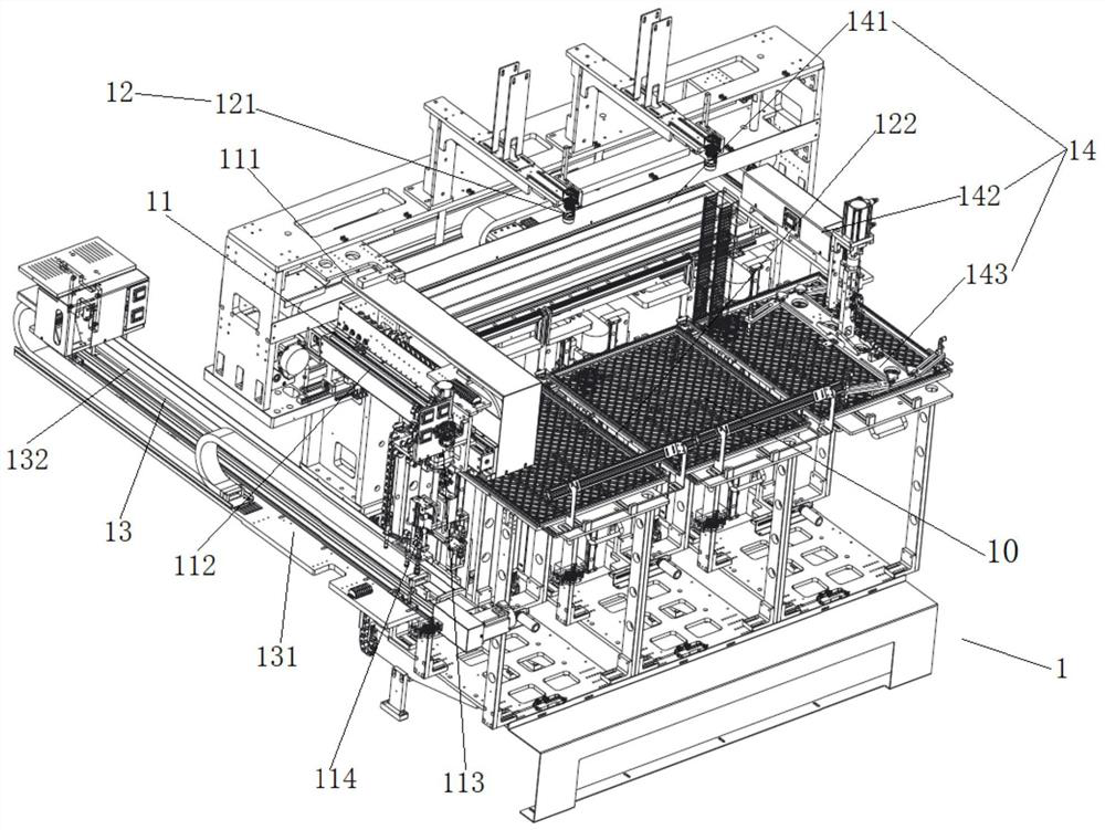
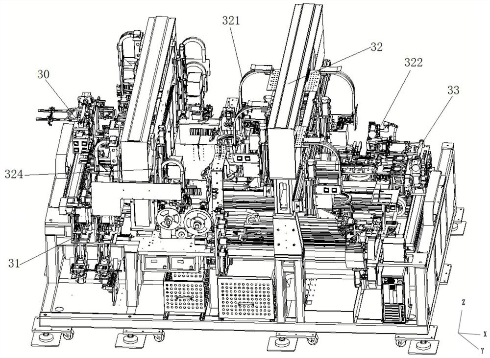
The invention relates to the technical field of automatic mechanical equipment, in particular to a laminating machine and a laminating method. The laminating machine comprises a first feeding module, a dispensing module, a soft-to-hard laminating module, a hard-to-hard laminating module, a film tearing and cleaning module, a second feeding module, a finished product detection module and a finished product discharging module, wherein the first feeding module is used for feeding a display module; the second feeding module is used for feeding a glass cover plate; the dispensing module is located between the first feeding module and the soft-to-hard laminating module, and the display module is sequentially conveyed to the first feeding end of the hard-to-hard laminating module along the first feeding module, the dispensing module and the soft-to-hard laminating module; the film tearing and cleaning module is located between the second feeding module and the hard-to-hard laminating module, and the glass cover plate is sequentially conveyed to the second feeding end of the hard-to-hard laminating module along the second feeding module and the film tearing and cleaning module; and the finished product detection module and the finished product discharging module are sequentially arranged at the discharging end of the hard-to-hard attaching module. According to the laminating machine, the production efficiency can be improved, and the labor intensity of workers can be reduced.

Description

technical field [0001] The invention relates to the technical field of automatic mechanical equipment, in particular to a laminating machine and a laminating method. Background technique [0002] OCA laminating machine, also known as "vacuum OCA laminating machine" or "touch screen OCA laminating machine", is one of the equipment used for screen laminating. The bonding principle is to place the LCD screen and the glass cover in a vacuum box in a vacuum environment, use the cylinder pressure of the machine to lower the inner mold of the vacuum cylinder, and completely press the glass cover and the LCD screen placed on the lower mold of the vacuum cylinder , so as to complete the key process of screen repair, that is, "OCA bonding process". [0003] In the existing laminating machines for wearable watches, most of the loading and unloading processes for materials such as wearable display modules, OCA optical adhesives, and wearable glass covers are still manually operated, wh...

Claims


Application Information

Patent Timeline
Patent Type & Authority Applications(China)
IPC IPC(8): G02F1/13B65G47/91
CPCG02F1/1303B65G47/912
Inventor 胡家宇
Owner 东莞市鼎力自动化科技有限公司
Learn More