Sandstone screening equipment for building construction

A technology for construction and screening equipment, which is applied in the direction of filter screen, solid separation, grille, etc. It can solve the problems of screen blockage, large-size sand and gravel that cannot be effectively used, and large-size sand and gravel that cannot be crushed and processed. Achieve the effect of solving easy blockage

Inactive Publication Date: 2021-04-30
邹福全
View PDF9 Cites 2 Cited by
  • Summary
  • Abstract
  • Description
  • Claims
  • Application Information

AI Technical Summary

Problems solved by technology

However, this device cannot crush large-sized gravel, resulting in the inability to effectively utilize large-sized gravel, and the device lacks parts for cleaning the screen, which easily leads to blockage of the screen

Method used


Image

  • Sandstone screening equipment for building construction
  • Sandstone screening equipment for building construction
  • Sandstone screening equipment for building construction

Examples


Embodiment 1

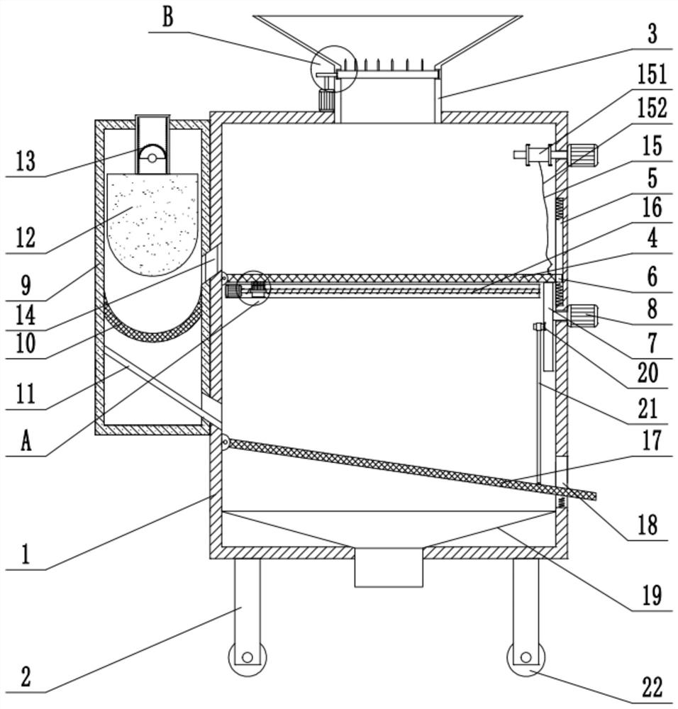
[0025] see Figure 1-5 , a kind of sand and gravel screening equipment for building construction, comprising a box body 1, supporting legs 2 are fixedly installed around the bottom of the box body 1, and a feeding funnel 3 extending to the inside of the box body 1 is fixedly installed on the top of the box body 1, and the box body 1. The first filter plate 4 is installed on the inner left wall. The right wall of the box body 1 is provided with a vertical groove 5. A slider 6 fixedly connected to the right side wall of the first filter plate 4 is slidably installed in the vertical groove 5. The box body 1. A motor 8 is fixedly installed on the right side wall. The output shaft of the motor 8 extends into the box body 1 and a cam 7 close to the right bottom wall of the first filter plate 4 is fixedly installed. The box body 1 on the left side of the first filter plate 4 The side wall is provided with a first discharge port 14, and the left side wall of the box body 1 is fixedly ...

Embodiment 2

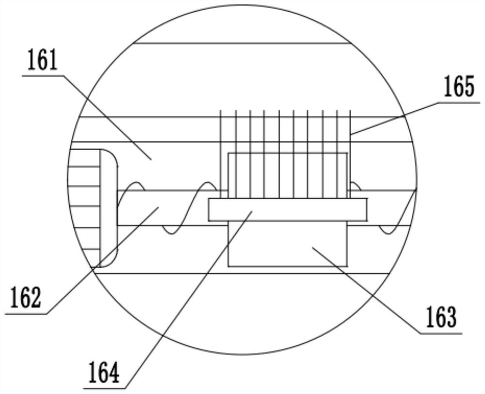
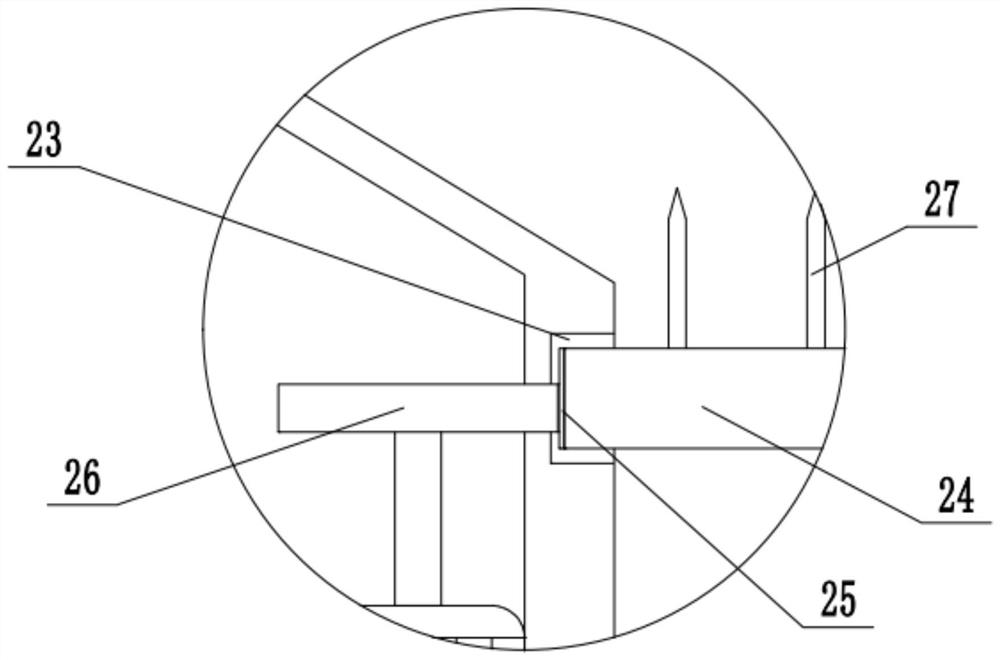
[0027]On the basis of Embodiment 1, an annular groove 23 is provided on the circumferential inner wall of the feeding funnel 3, and a blanking plate 24 is slidably installed in the annular groove 23, and a toothed ring 25 is fixedly installed on the circumferential side wall of the blanking plate 24, and the box body 1. A motor 8 is fixedly installed on the top, and the output shaft of the motor 8 is fixedly installed with a gear plate 26 meshed with the gear ring 25. The top of the blanking plate 24 is fixedly installed with multiple groups of stirring cones 27 distributed at intervals from the blanking holes. The disc 26 meshes with the gear ring 25 to drive the lower material plate 24 to rotate and cooperate with the stirring cone 27 to effectively control the falling speed of the sand and prevent the sand from being blocked in the feeding funnel 3. The vibrating part 13 includes a vibrating The U-shaped frame 131 that is fixedly installed upwards on the top of the smashing ...


PUM


Abstract

The invention belongs to the technical field of building construction, and discloses sandstone screening equipment for building construction. According to the technical key points, the sandstone screening equipment for the building construction comprises a box body, a first filter plate is rotatably mounted on the left wall in the box body, a vertical groove is formed in the right wall in the box body, and a slide block fixedly connected with the right side wall of the first filter plate is slidably mounted in the vertical groove; a motor is fixedly installed on the right side wall of the box body, an output shaft of the motor extends into the box body and is fixedly provided with a cam tightly attached to the right bottom wall of the first filter plate, a first discharging opening is formed in the side wall of the box body on the left side of the first filter plate, and a smashing box communicating with the box body through the first discharging opening is fixedly installed on the left side wall of the box body; and an arc-shaped mashing plate is fixedly installed in the smashing box, a vibrating column is slidably installed in the smashing box above the mashing plate, the top end of the vibrating column is connected with a vibrating component, a hole cleaning component is installed between the front inner wall and the rear inner wall of the box body below the first filter plate, and the right bottom of the first filter plate is upwards connected with a lifting component.

Description

technical field [0001] The invention relates to the technical field of building construction, in particular to sand and gravel screening equipment for building construction. Background technique [0002] On the construction site, sand and gravel are often used. Since the particle size of the sand and gravel is uneven when the sand and gravel is bought, it is necessary to screen the sand and gravel through screening equipment. The sand and gravel screening equipment used in construction in the prior art is usually manually screened through a screen or a sieve plate. The strength is high, the screening efficiency is slow, and it is not convenient for people to screen and use. [0003] In order to solve the above problems, the Chinese patent (notification number: CN 112024398 A, announcement date: 2020.12.04) discloses a construction sand and gravel screening equipment, which can divide sand and gravel into large, Medium and small gravel in different sizes. However, the devi...

Claims


Application Information

Patent Timeline
Patent Type & Authority Applications(China)
IPC IPC(8): B02C1/14B02C23/16B07B1/04B07B1/28B07B1/42B07B1/52
CPCB02C1/14B02C23/16B07B1/04B07B1/28B07B1/42B07B1/522
Inventor 邹福全
Owner 邹福全
Why Eureka
Try Eureka