
Motor rotor and built-in rotor permanent magnet motor

A technology of motor rotor and permanent magnet motor, which is applied in the direction of electromechanical devices, magnetic circuits, electrical components, etc., and can solve the problems of inability to balance electromagnetic performance and structural strength

Inactive Publication Date: 2021-04-27
CSR ZHUZHOU ELECTRIC LOCOMOTIVE RES INST
View PDF7 Cites 1 Cited by
  • Summary
  • Abstract
  • Description
  • Claims
  • Application Information

AI Technical Summary

Problems solved by technology

[0004] In view of this, the object of the present invention is to propose a motor rotor and a built-in rotor permanent magnet motor to solve the problem that the existing magnetic isolation bridge design cannot take into account both electromagnetic performance and structural strength

Method used


Image

  • Motor rotor and built-in rotor permanent magnet motor
  • Motor rotor and built-in rotor permanent magnet motor
  • Motor rotor and built-in rotor permanent magnet motor

Examples


Embodiment Construction

[0026] In order to make the object, technical solution and advantages of the present invention clearer, the present invention will be described in further detail below in conjunction with specific embodiments and with reference to the accompanying drawings.

[0027] It should be noted that, unless otherwise defined, the technical terms or scientific terms used in the embodiments of the present invention shall have the usual meanings understood by those skilled in the art to which the present disclosure belongs. "First", "second" and similar words used in the present disclosure do not indicate any order, quantity or importance, but are only used to distinguish different components. "Comprising" or "comprising" and similar words mean that the elements or items appearing before the word include the elements or items listed after the word and their equivalents, without excluding other elements or items. Words such as "connected" or "connected" are not limited to physical or mechan...


PUM


Abstract

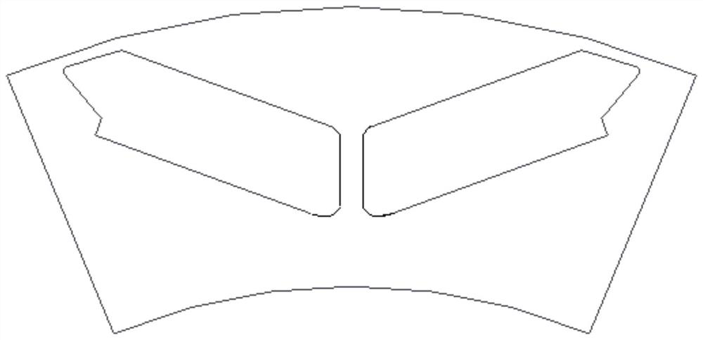
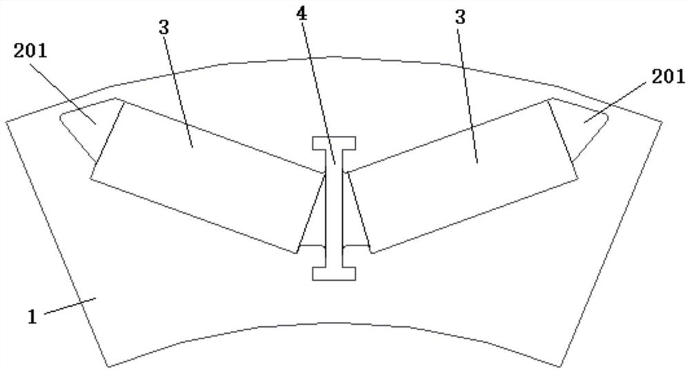
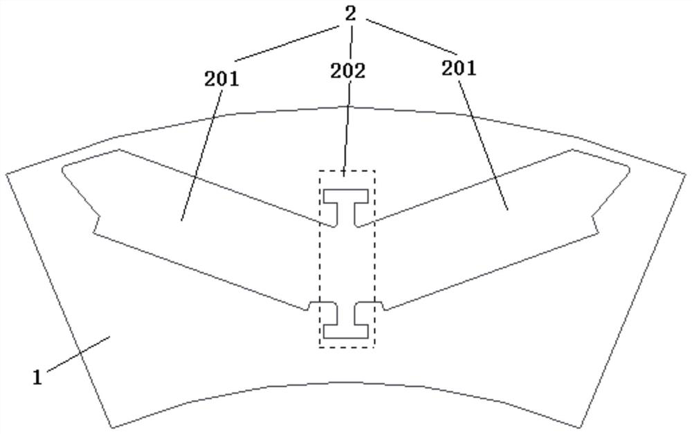
The invention provides a motor rotor and a built-in rotor permanent magnet motor. The motor rotor comprises a rotor body; the rotor body is provided with a plurality of mounting groove units, and the plurality of mounting groove units are uniformly distributed along the circumferential direction of the rotor body; the mounting groove unit comprises a permanent magnet mounting groove in which a permanent magnet is mounted and a magnetic isolation bridge mounting groove in which a magnetic isolation bridge single body is mounted; the number of the permanent magnet mounting grooves is at least two, and one magnetic isolation bridge mounting groove is formed between any two adjacent permanent magnet mounting grooves. The design of integrally forming and manufacturing the magnetic isolation bridge in the prior art is improved, the magnetic isolation bridge single bodies are mounted through the magnetic isolation bridge mounting grooves in the rotor body to form a magnetic isolation bridge structure, and meanwhile, by reasonably selecting the materials of the magnetic isolation bridge single bodies, the structural strength of the magnetic isolation bridge can be improved, and meanwhile, the electromagnetic performance is effectively ensured.

Description

technical field [0001] The invention relates to the technical field of motors, in particular to a motor rotor and a built-in rotor permanent magnet motor. Background technique [0002] With the country's vigorous promotion and popularization of new energy vehicles, the performance and energy saving requirements of vehicle drive motors are getting higher and higher. In the built-in rotor permanent magnet motor commonly used in new energy vehicles, the magnetic isolation bridge structure will affect many operating parameters, and is one of the key designs in the built-in rotor permanent magnet motor. [0003] In the existing magnetic isolation bridge design, in order to prevent demagnetization caused by rotor magnetic leakage, the magnetic isolation bridge is usually designed to be relatively thin and the structural strength is insufficient, which makes the rotor rotate at high speed during operation, and the thinner magnetic isolation bridge will bear a lot of pressure. Larg...

Claims


Application Information

Patent Timeline
Patent Type & Authority Applications(China)
IPC IPC(8): H02K1/27
CPCH02K1/276
Inventor 崔龙卢小龙史俊旭李华湘史文波李蓉
Owner CSR ZHUZHOU ELECTRIC LOCOMOTIVE RES INST
Learn More