
Electronic transformer output voltage stable variator

An electronic transformer and output voltage technology, which is applied in the substation/power distribution device casing, electrical components, circuit devices, etc., can solve the problems of huge ground generation, affecting the normal operation of the factory area, and vibration of the main body of the equipment.

Pending Publication Date: 2021-04-23
南京丰旭电子科技有限公司
View PDF0 Cites 0 Cited by
  • Summary
  • Abstract
  • Description
  • Claims
  • Application Information

AI Technical Summary

Problems solved by technology

[0002] The voltage stabilizing variable is mostly used in industrial factories, and has the advantages of stable voltage transmission effect, small footprint, and simple operation; but the existing voltage stabilizing variable still has certain disadvantages in use. When the variable is used in the heavy industry factory area, because the heavy industrial factory enters the factory and will deal with relatively large heavy industrial workpieces, the ground will generate a huge shock force. Stable voltage transmission affects the normal operation of the factory area. Secondly, when the power is suddenly cut off in the factory area, it is necessary to check the circuit situation. The dark environment is not convenient for users to check the main body of the equipment and the internal passages of the factory area. Therefore, we propose a An Electronic Transformer Output Voltage Stabilizer

Method used


Image

  • Electronic transformer output voltage stable variator
  • Electronic transformer output voltage stable variator
  • Electronic transformer output voltage stable variator

Examples


Embodiment Construction

[0018] In order to make the technical means, creative features, goals and effects achieved by the present invention easy to understand, the present invention will be further described below in conjunction with specific embodiments.

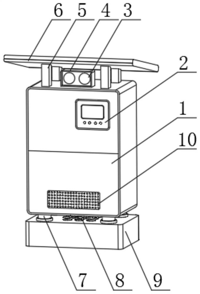
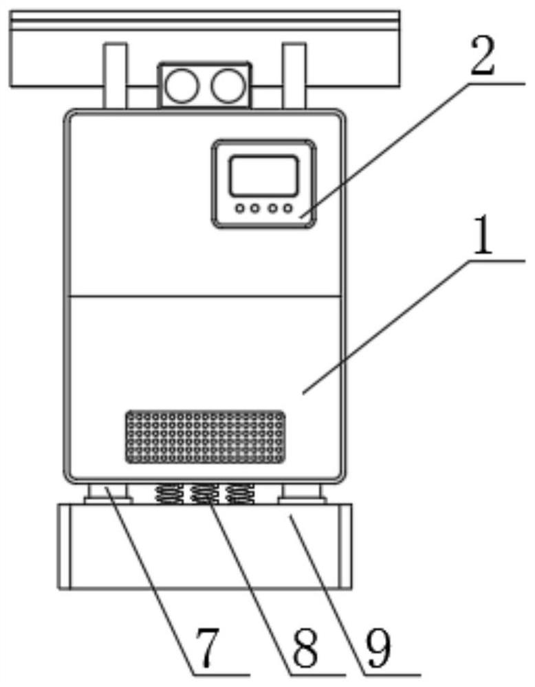
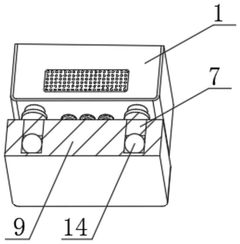
[0019] Such as Figure 1-4 As shown, an electronic transformer output voltage stabilizing variable device includes a device main body 1, a heat dissipation hole 10 is provided on the front outer surface of the device main body 1, a display screen 2 is arranged on the upper end of the heat dissipation hole 10, and a lower end outer surface of the device main body 1 A shock-absorbing spring 8 is provided, the side end of the shock-absorbing spring 8 is provided with a shock-absorbing rod 7, the lower end of the shock-absorbing spring 8 is provided with a shock-absorbing base 9, and the outer surface of the upper end of the equipment main body 1 is provided with a lighting lamp holder 4, and the lighting lamp The outer surface of the front end of the...


PUM


Abstract

The invention discloses an electronic transformer output voltage stable variator which comprises an equipment main body, wherein heat dissipation holes are formed in the outer surface of the front end of the equipment main body, a display screen is arranged at the upper ends of the heat dissipation holes, damping springs are arranged on the outer surface of the lower end of the equipment main body, damping rods are arranged at the side ends of the damping springs, a damping base is arranged at the lower end of the damping spring, an illuminating lamp holder is arranged on the outer surface of the upper end of the equipment main body, an illuminating lamp bead is embedded in the outer surface of the front end of the illuminating lamp holder, a supporting rod is arranged at the side end of the illuminating lamp holder, and a protective baffle is arranged at the upper end of the supporting rod. According to the electronic transformer output voltage stable variator, through cooperation of the damping rods, the damping air bags and the damping springs, vibration borne by the equipment main body can be effectively reduced, and therefore the situation that due to vibration, voltage transmission of the equipment main body is unstable is avoided, and a user can conveniently check the situation in case of power failure through utilizing the illuminating lamp bead.

Description

technical field [0001] The invention relates to the field of electric power transmission, in particular to an output voltage stabilizing variabler of an electronic transformer. Background technique [0002] The voltage stabilizing variable is mostly used in industrial factories, and has the advantages of stable voltage transmission effect, small footprint, and simple operation; but the existing voltage stabilizing variable still has certain disadvantages in use. When the variable is used in the heavy industry factory area, because the heavy industrial factory enters the factory and will deal with relatively large heavy industrial workpieces, the ground will generate a huge shock force. Stable voltage transmission affects the normal operation of the factory area. Secondly, when the power is suddenly cut off in the factory area, it is necessary to check the circuit situation. The dark environment is not convenient for users to check the main body of the equipment and the inter...

Claims


Application Information

Patent Timeline
IPC IPC(8): H02B1/26H02B1/56H02B1/50H02B1/54H02J9/02
CPCH02B1/26H02B1/50H02B1/54H02B1/56H02B1/565H02J9/02
Inventor 韦峰孙刚陈雪红
Owner 南京丰旭电子科技有限公司
Learn More