Control system of electric shunt valve and control method thereof

An electric water diversion valve and control system technology, applied in the general control system, control/regulation system, program control, etc., can solve the problems of cramped bathtub space, water pressure loss, noise, etc., and achieve precise control, simplified operation, The effect of improving user experience

Pending Publication Date: 2021-04-23
GUANGZHOU RISING DRAGON ELECTRONICS & PLASTICS TECH
View PDF0 Cites 0 Cited by
  • Summary
  • Abstract
  • Description
  • Claims
  • Application Information

AI Technical Summary

Problems solved by technology

[0002] The common water diversion valve on the market is manually adjusted. The disadvantage is that, due to the high pressure of the water to be adjusted, it takes a lot of effort to twist the valve core, which is inconvenient for children or women to use; The knob and spool of the regulating valve must be connected coaxially, which requires a larger space for installation above the back of the cylinder, and this place is where the space of the bathtub is relatively cramped; again, due to the installation of the manual regulating valve At the top of the tank, the water must be adjusted from the bottom of the tank to the top of the tank through pipes, resulting in a loss of water pressure. The knob of the regulating valve is generally high, which is a drag on the appearance of the bathtub and the design of the bathtub. Therefore, the market proposes an electric water diversion valve with a control panel and driven by a motor to rotate the spool. However, the electric water diversion valve is directly operated by Electric drive needs to be adapted to the control system and control method. The control system needs to ensure that the spool can be controlled by the control panel to rotate to the position required by the customer, and the control system needs to accurately detect the position of the spool. When the spool is misaligned It can be corrected in time, therefore, the present invention proposes a control system and control method for an electric water diversion valve

Method used


Image

  • Control system of electric shunt valve and control method thereof
  • Control system of electric shunt valve and control method thereof
  • Control system of electric shunt valve and control method thereof

Examples


Embodiment Construction

[0044] A control system and a control method of an electric water diverter valve provided by the present invention will be further described below with reference to the accompanying drawings. It should be pointed out that the technical solution and design principle of the present invention are only described below with an optimized technical solution. elaborate.

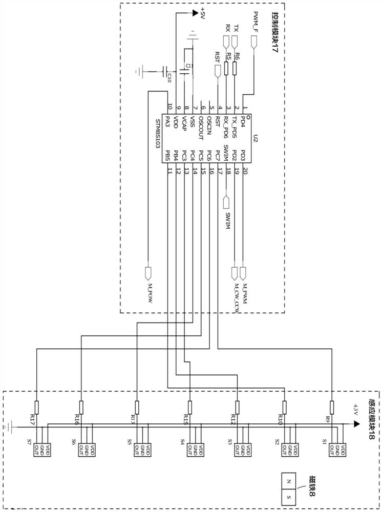
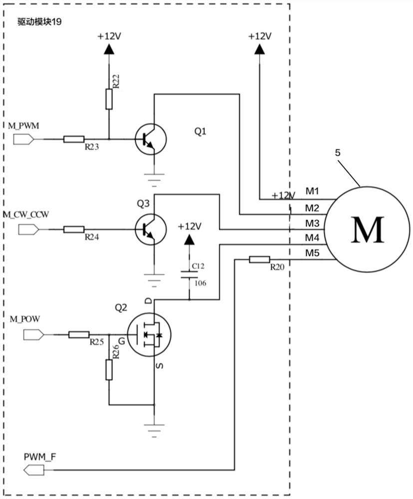
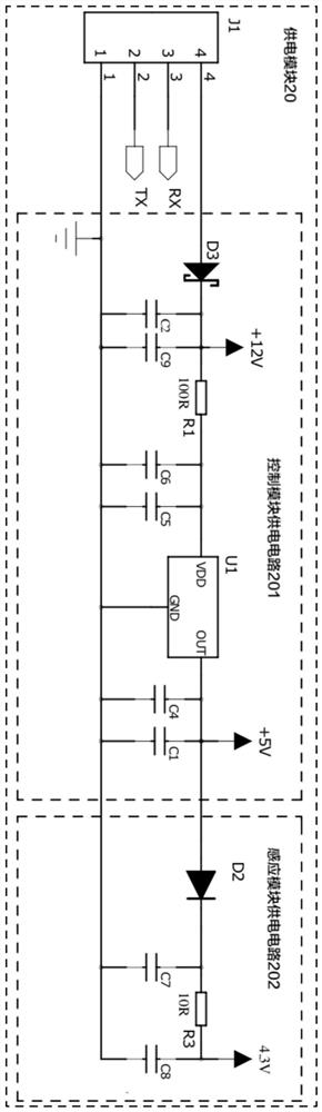
[0045] see figure 1 , figure 2 and image 3 The present invention provides a control system for an electric water diverter valve, comprising a power supply module 20, a control module 17, an induction module 18 and a drive module 19, wherein the power supply module 20 is electrically connected to the control module 17, The power supply module 20 is used to provide power to the control module 17 and the induction module 18; the control module 17 is also electrically connected to the induction module 18 and the driving module 19, and the control module 17 is used to provide the driving module 19 according to the con...


PUM


Abstract

The invention provides a control system of an electric shunt valve and a control method thereof. The control system comprises a power supply module, a control module, a sensing module and a driving module, the power supply module is electrically connected with the control module, and the power supply module is used for providing electric energy for the control module and the sensing module; the control module is further electrically connected with the sensing module and a driving module, and the control module is used for sending a motor driving signal to the driving module according to the control information of the control button, receiving a valve element position signal fed back by the induction module and a motor position signal fed back by the driving module and correcting the positions of the valve element and the motor; the sensing module is used for collecting the position of the valve element and feeding back a valve element position signal to the control module. The driving module is used for receiving a motor driving signal, driving the motor to execute actions, receiving a motor position signal fed back by the motor and sending the motor position signal to the control module; the control method comprises a control method of the control module and a control method of the driving module.

Description

technical field [0001] The invention relates to a control system and a control method of a water diverter valve, in particular to a control system of an electric water diverter valve and a control method thereof. Background technique [0002] The common diverter valve on the market is manual adjustment. The knob and spool of the regulating valve must be connected coaxially, which requires a larger space above the back of the cylinder for installation, and this place is where the bathtub space is relatively cramped; again, due to the installation of the manual regulating valve At the top of the cylinder, the water must be adjusted from the bottom of the cylinder to the top of the cylinder through pipes, resulting in a loss of water pressure. At the same time, due to the water flow through the valve body through the bend, the turbulent flow causes noise in the valve body; The knob of the regulating valve is generally high, which is a drag on the beauty of the bathtub and the ...

Claims


Application Information

Patent Timeline
Patent Type & Authority Applications(China)
IPC IPC(8): G05B19/042
CPCG05B19/0423G05B2219/24215
Inventor 戴忠果郭孜勤梁波吴应均
Owner GUANGZHOU RISING DRAGON ELECTRONICS & PLASTICS TECH
Why Eureka
Try Eureka