Dynamic to-be-measured object angle measuring instrument and measuring method

A technology for measuring angles and objects to be measured, applied to measuring devices, instruments, and optical devices, etc., can solve problems such as low efficiency, inability to measure efficiently in real time, and reduce the timeliness of data collection

Active Publication Date: 2021-04-23
ISVISION (TIANJIN) TECH CO LTD
View PDF11 Cites 2 Cited by
  • Summary
  • Abstract
  • Description
  • Claims
  • Application Information

AI Technical Summary

Problems solved by technology

The existing method for testing the angle between a large-sized object to be measured (more than 10 meters in size) and additional equipment is the vertical target method. This method is a manual measurement method. The entire measurement process takes more than several hours and requires more than ten meters. It can only be completed with the assistance of multiple people at the same time. The operation is complicated, the efficiency is low, the requirements for the environment are high, and it is impossible to measure the dynamic measured object.
[0003] Existing technologies and equipment require the measured object to be measured in an absolutely stable environment. If it is aimed at a dynamic measured object or on a carrying platform, it cannot be tested, which greatly limits the application range of angle measurement and cannot be obtained in many fields. High-precision angle measurement data; and cannot perform real-time measurement efficiently, greatly reducing the timeliness of data collection

Method used


Image

  • Dynamic to-be-measured object angle measuring instrument and measuring method
  • Dynamic to-be-measured object angle measuring instrument and measuring method
  • Dynamic to-be-measured object angle measuring instrument and measuring method

Examples


Embodiment Construction

[0043] The technical solutions of the present invention will be described in detail below in conjunction with the accompanying drawings and specific embodiments.

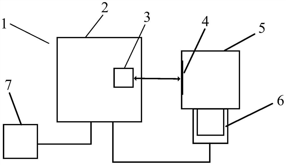
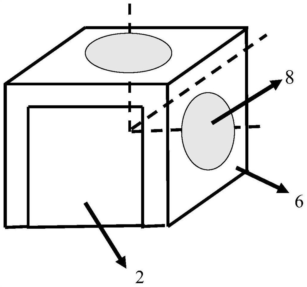
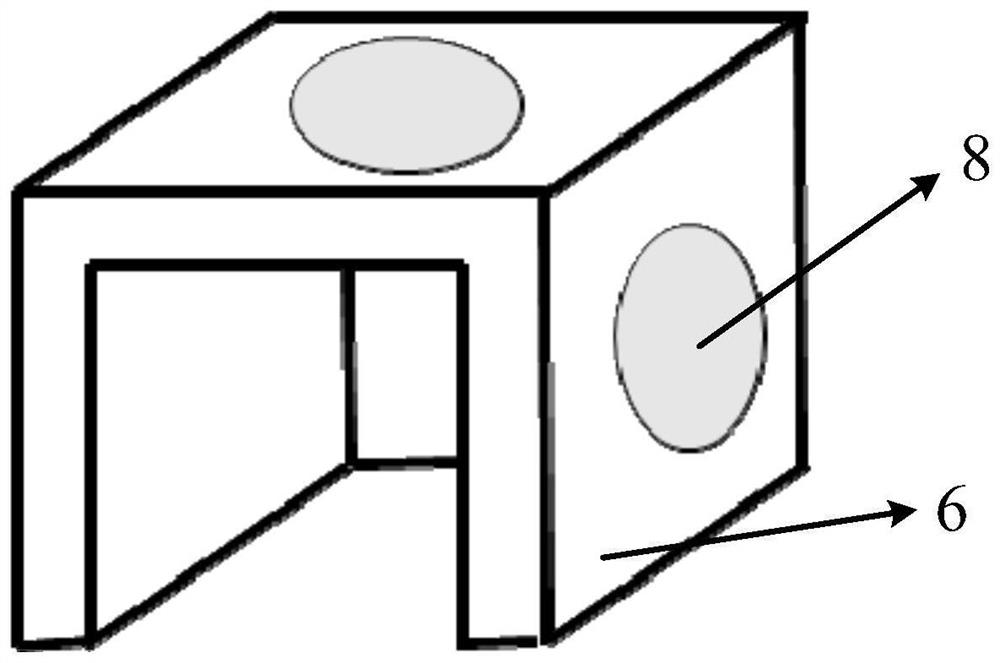
[0044] A dynamic object angle measuring instrument, comprising a reference inertial navigation system 6, a small angle measurement system 3 and a dynamic inertial navigation system 2;

[0045] The reference inertial navigation system 6 is installed on the object to be measured 5, and is used to feed back the attitude information of the object to be measured 5;

[0046] The small-angle measurement system 3 and the dynamic inertial navigation system 2 are integrated, and the relative positions of the two remain unchanged, forming the measurement component A1; the dynamic inertial navigation system is used to obtain the position information of the measurement component A1, and the small-angle measurement system 3 is used to obtain the position information of the measurement component A1. Angle information of object 5; ...


PUM


Abstract

The invention provides a dynamic to-be-measured object angle measuring instrument and a measuring method. The measuring instrument comprises a reference inertial navigation system, a small-angle measuring system and a dynamic inertial navigation system, the reference inertial navigation system is installed on an object to be measured and used for feeding back attitude information of the object to be measured. The small-angle measurement system and the dynamic inertial navigation system are integrally arranged and are unchanged in relative position to form a measurement component A; the dynamic inertial navigation system is used for acquiring position information of the measurement component A; the small-angle measuring system is used for acquiring angle information of an object to be measured; the centers of coordinate systems of the reference inertial navigation system, the small-angle measurement system and the dynamic inertial navigation system coincide, and the coordinate systems of the three systems are unified under an equipment coordinate system. The technical scheme provided by the invention can realize angle measurement when the object to be measured and a carrying platform synchronously move, does not need multi-person cooperation measurement, can be operated by a single person, only needs 1 min in the measurement process, is high in measurement efficiency, and is suitable for various test scenes.

Description

technical field [0001] The invention relates to the field of angle measurement, in particular to a dynamic measuring object angle measuring instrument and a measuring method. Background technique [0002] At present, angle measurement is an important part of metrology and is widely used in the field of industrial production. For example, in large-scale machinery manufacturing and engineering installation, it is often necessary to measure different-plane geometric elements (such as shaft axes, holes, etc.) The space angle between the center line of the plate and the normal line of the plate). Such requirements involve spatial angle measurement at larger spacings. Traditional angle measurement methods such as three-coordinate measuring machine method, multi-station theodolite method, and collimator measurement method have certain limitations in measurement accuracy and application range, and all require the measured object to remain in a static and stable state. The existing...

Claims


Application Information

Patent Timeline
Patent Type & Authority Applications(China)
IPC IPC(8): G01B11/26
CPCG01B11/26
Inventor 尹仕斌郭寅郭磊邹剑
Owner ISVISION (TIANJIN) TECH CO LTD
Why Eureka
Try Eureka