Virtual optical network reconfiguration method and system

A virtual optical network and reconfiguration technology, which is applied to the selection device, selection device, electrical components and other directions of the multiplexing system. To avoid the risk of business traffic congestion, save energy consumption, and improve resource utilization

Active Publication Date: 2021-04-20
BEIJING UNIV OF POSTS & TELECOMM
View PDF12 Cites 0 Cited by
  • Summary
  • Abstract
  • Description
  • Claims
  • Application Information

AI Technical Summary

Problems solved by technology

[0008] The purpose of the present invention is to provide a virtual optical network reconfiguration method and system to solve tenants’ lack of understanding of the flexibility of the optical layer. Tenants often regard the flexible optical network as a static pipeline and cannot use the flexibility of the optical network, resulting in Low utilization of network resources caused by static network topology in virtual optical network

Method used


Image

  • Virtual optical network reconfiguration method and system
  • Virtual optical network reconfiguration method and system
  • Virtual optical network reconfiguration method and system

Examples


Embodiment Construction

[0063] The following will clearly and completely describe the technical solutions in the embodiments of the present invention with reference to the accompanying drawings in the embodiments of the present invention. Obviously, the described embodiments are only some, not all, embodiments of the present invention. Based on the embodiments of the present invention, all other embodiments obtained by persons of ordinary skill in the art without making creative efforts belong to the protection scope of the present invention.

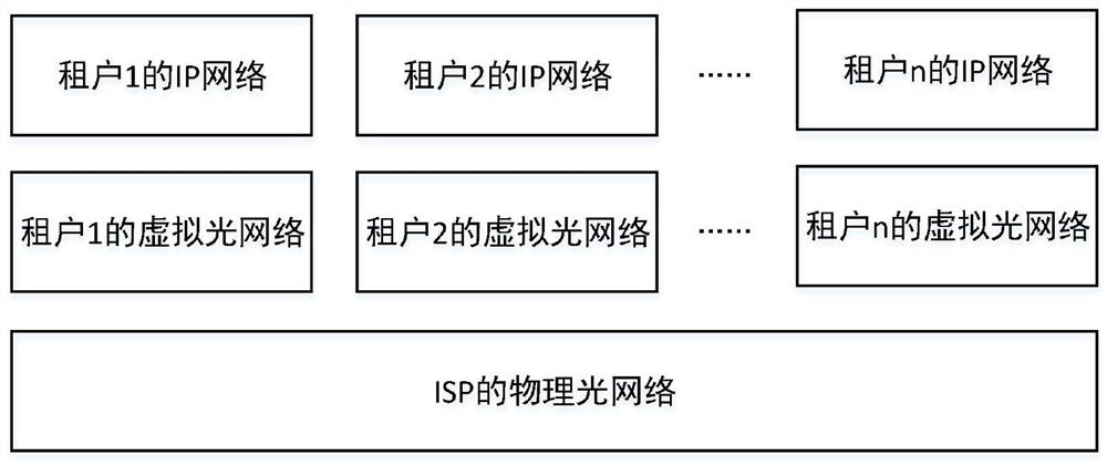
[0064] The purpose of the present invention is to provide a virtual optical network reconfiguration method and system, which discloses optical layer capabilities to IP layer tenants corresponding to each IP network controller, so as to realize the disclosure of optical network flexibility capabilities to tenants, without notifying optical layer resources Under the premise, the topology structure of the virtual optical network can be dynamically adjusted accordi...


PUM


Abstract

The invention relates to a virtual optical network reconfiguration method and system. The virtual optical network reconfiguration method comprises the following steps: acquiring a bandwidth demand matrix by using the optical layer controller; configuring the optical network device by taking meeting the bandwidth requirement matrix as a target, and determining an optimal topological structure with a management target; recommending the optimal topological structure with the management target to the IP network controller; judging whether the IP network controller accepts the optimal topological structure with the management target or not, and if so, executing the optimal topological structure with the management target; and if not, re-estimating the bandwidth demand matrix by using the optical layer controller until the IP network controller accepts the optimal topological structure with the management target. The resource utilization rate can be improved.

Description

technical field [0001] The invention relates to the field of virtual optical network reconfiguration, in particular to a virtual optical network reconfiguration method and system. Background technique [0002] Thanks to the advantages of low cost, large capacity, and low latency of optical networks, optical networks are widely used in telecommunication networks. Network topology represents the connection relationship between network nodes and the maximum carrying capacity of each connection. figure 1 It is the structural diagram of the telecommunication network, such as figure 1 As shown, the Internet Service Provider (Internet Service Provider, ISP) abstracts the complex underlying hardware facilities into a simple virtual optical network topology through the virtual optical network technology to provide transport services for the tenant's IP network, carry the tenant's IP traffic, and make the Multiple tenants can share the same physical optical network; in order to avoid...

Claims


Application Information

Patent Timeline
IPC IPC(8): H04Q11/00
Inventor 顾仁涛李哲康纪越峰
Owner BEIJING UNIV OF POSTS & TELECOMM
Why Eureka
Try Eureka