


Quick Research
Generate reliable direction feasibility study reports for your R&D in just a few steps.

Technical Q&A
Discover and master advanced knowledge NOW. Basics, ideas, possibilities, all at once.

Find Solutions
As an expert in R&D theories, this can generate solutions to your technical problems instantly.

Evaluate Feasibility
Analyze your overall solution with one click, know your potential R&D risks in advance.

Monitor Landscape
Get weekly tech updates, stay abreast of the latest tech innovations and key insights.
Brake sucker device shrunk under automobile chassis and braking method thereof
A car chassis and suction cup technology, applied in the direction of brakes, braking components, vehicle components, etc., can solve problems such as threatening the life safety of drivers, passengers, passers-by, etc., and achieve the effect of shortening braking distance, good application prospects, and fast response.
- Summary
- Abstract
- Description
- Claims
- Application Information
AI Technical Summary
Problems solved by technology
Method used
Image

Examples
Embodiment 1
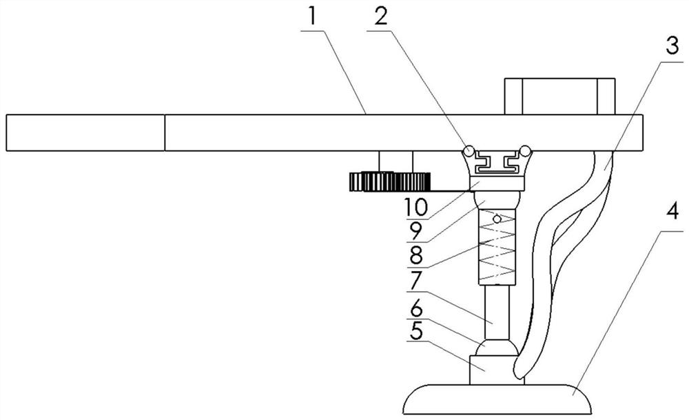
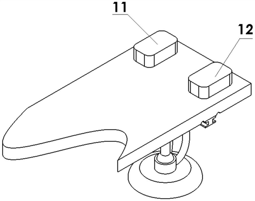
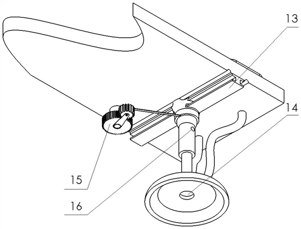
[0029] Such as figure 1 , 2, shown in 3 and 4, the brake sucker device that shrinks below the automobile chassis includes an I-shaped slide rail 13, a sucker assembly, a trachea 3, a vacuum pump 11, an air pump 12, a motor, a gear crank slider mechanism 15 and a pressure sensor; The glyph slide rail 13 is fixed on the bottom surface of the automobile chassis 1, is positioned at the rear position of the automobile chassis, and is arranged near the wheel drive shaft; the pressure sensor is fixed on the upper surface of the foot brake; Hinge one and ball hinge two; Shrink rod 7 comprises outer cylinder, inner rod, piston 17 and spring 8; Outer cylinder is provided with pressure relief hole 16 and air inlet; The piston cavity between 17 is connected; the piston and the outer cylinder form a sliding pair; the high-pressure pump is fixed on the top surface of the automobile chassis 1; the piston 17 is fixed to the inner end of the inner rod; the two ends of the spring 8 are respect...
Embodiment 2
[0033] Such as Figure 4 , 6 , 7 and 8, the brake suction cup device shrunk below the chassis of the car, including a suction cup assembly, air pipe 3, transition chamber 20, vacuum pump 11, air pump 12 and pressure sensor; three shrink rod fixing supports 19 are arranged in a triangle cloth, and are all fixed on the bottom surface of the automobile chassis 1; one of the retractable rod fixed supports 19 is located in the middle of the automobile chassis 1, and the other two retractable rod fixed supports 19 are arranged near the rear wheel drive shaft; the pressure sensor is fixed on the upper surface of the foot brake; The suction cup assembly includes a suction cup 4, an ultrasonic detector 14, a shrink rod 7, a ball hinge one and a ball hinge two; the shrink rod 7 includes an outer cylinder, an inner rod, a piston 17 and a spring 8; the outer cylinder is provided with a pressure relief hole 16 and an air intake hole; the air inlet is communicated with the piston cavity be...
PUM
 Abstract
Description
Claims
Application Information
 - R&D Engineer
- R&D Manager
- IP Professional
- Industry Leading Data Capabilities
- Powerful AI technology
- Patent DNA Extraction
Browse by: Latest US Patents, China's latest patents, Technical Efficacy Thesaurus, Application Domain, Technology Topic, Popular Technical Reports.
© 2024 PatSnap. All rights reserved.Legal|Privacy policy|Modern Slavery Act Transparency Statement|Sitemap|About US| Contact US: help@patsnap.com