
Enhanced rubber extrusion feeding device

A feeding device, enhanced technology, applied in the field of enhanced rubber extrusion feeding device, can solve the problems of easy agglomeration of materials, lower work efficiency, inconvenient manual operation, etc., to avoid accumulation and agglomeration, and improve production efficiency and quality, the effect of avoiding manual operation

Inactive Publication Date: 2021-04-16
台州耘智科技有限公司
View PDF5 Cites 0 Cited by
  • Summary
  • Abstract
  • Description
  • Claims
  • Application Information

AI Technical Summary

Problems solved by technology

[0004] The purpose of the present invention is to solve the problem that in the existing rubber production equipment, workers often need to intermittently feed materials according to production requirements, which greatly increases the workload, and the manual operation is inconvenient, and the accumulation of materials is easy to agglomerate, which greatly reduces the Shortcomings of work efficiency, and proposed an enhanced rubber extrusion feeding device

Method used


Image

  • Enhanced rubber extrusion feeding device
  • Enhanced rubber extrusion feeding device
  • Enhanced rubber extrusion feeding device

Examples


Embodiment 1

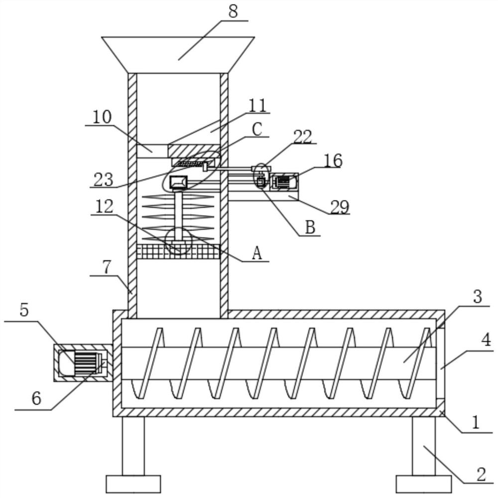
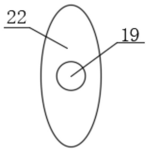
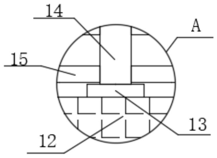
[0026] refer to Figure 1-5 , an enhanced rubber extrusion feeding device, comprising a box body 1, two brackets 2 are symmetrically and fixedly installed on the bottom of the box body 1, an extruding screw 3 is installed in rotation in the box body 1, and one side of the box body 1 is opened There is a discharge hole 4, and the other side of the box body 1 is fixedly installed with a first drive motor 5, and a drive shaft 6 is fixedly installed on the output shaft of the first drive motor 5, and the drive shaft 6 is far away from the output shaft of the first drive motor 5. One end is fixedly connected with the extruding screw 3, a treatment box 7 is fixedly installed on the top of the box body 1, a material guide cover 8 is fixedly installed on the top of the treatment box 7, a partition 9 is fixedly installed in the treatment box 7, and a Leakage 10 is arranged, the top of dividing plate 9 is fixedly installed with inclined plate 11, and filter screen 12 is fixedly installe...

Embodiment 2

[0035] refer to Figure 1-5 , a reinforced rubber extrusion feeding device, including a box 1, the bottom of the box 1 is symmetrically fixed with two brackets 2 by welding, the inside of the box 1 is rotated and installed with an extrusion screw 3, one part of the box 1 The side is provided with a discharge hole 4, and the other side of the box body 1 is fixed with a first drive motor 5 by screws, and a drive shaft 6 is fixedly installed on the output shaft of the first drive motor 5 by welding, and the drive shaft 6 is far away from the first drive shaft. One end of the output shaft of the driving motor 5 is fixedly connected with the extruding screw 3, the top of the box body 1 is fixedly installed with a treatment box 7 by welding, the top of the treatment box 7 is fixedly installed with a material guide cover 8 by welding, and the inside of the treatment box 7 is welded. A partition 9 is fixedly installed, and a leak hole 10 is provided on the partition 9. The top of the ...


PUM


Abstract

The invention belongs to the technical field of feeding devices, particularly relates to an enhanced rubber extrusion feeding device, and aims at solving the problems that in an existing rubber production device, intermittent feeding by workers is often needed according to production requirements, the workload is greatly improved, manual operation is inconvenient, materials are prone to caking due to accumulation and the working efficiency is greatly reduced. According to the scheme, the device comprises a box body, two supports are symmetrically and fixedly installed at the bottom of the box body, an extrusion screw is rotatably installed in the box body, a discharging hole is formed in one side of the box body, a first driving motor is fixedly installed on the other side of the box body, a driving shaft is fixedly installed on an output shaft of the first driving motor, and the end, away from the output shaft of the first driving motor, of the driving shaft is fixedly connected with the extrusion screw. According to the device, manual operation is avoided, time and labor are saved, accumulation and caking of materials are avoided, the discharging amount is controlled, and the production efficiency and quality of rubber are effectively improved.

Description

technical field [0001] The invention relates to the technical field of feeding devices, in particular to an enhanced rubber extrusion feeding device. Background technique [0002] In the prior art, extruders used for rubber production are generally of single-screw or multi-screw structure to extrude materials into shapes. [0003] However, in the existing rubber production equipment, workers often need to intermittently feed materials according to production requirements, which greatly increases the workload, and manual operation is inconvenient, and the accumulation of materials is easy to agglomerate, which greatly reduces work efficiency. Contents of the invention [0004] The purpose of the present invention is to solve the problem that in the existing rubber production equipment, workers often need to intermittently feed materials according to production requirements, which greatly increases the workload, and the manual operation is inconvenient, and the accumulation ...

Claims


Application Information

Patent Timeline
Patent Type & Authority Applications(China)
IPC IPC(8): B29C48/285B29B7/16B29B13/10
Inventor 刘义林王军华毛润东袁康杰
Owner 台州耘智科技有限公司
Learn More