Lug type tunnel gate for plastic pipefitting die

A technology of latent gate and plastic pipe fittings, which is applied in the field of bump-type latent gate of plastic pipe fitting molds, can solve the problems of inability to reach at the same time, weld marks, affecting the appearance of products, etc. beautiful effect

Inactive Publication Date: 2021-04-16
TAIZHOU HUANGYAN WEIDA PLASTIC MACHINERY
View PDF5 Cites 0 Cited by
  • Summary
  • Abstract
  • Description
  • Claims
  • Application Information

AI Technical Summary

Problems solved by technology

However, in actual production, since the injection gate is below the parting line, the molten plastic raw material flows into the mold cavity from both sides after being injected from the gate. As a result, the two strands of plastic raw material cannot reach the intersection position at the same time. A certain temperature difference will easily produce weld marks during welding, which will affect the appearance of the product

Method used


Image

  • Lug type tunnel gate for plastic pipefitting die
  • Lug type tunnel gate for plastic pipefitting die
  • Lug type tunnel gate for plastic pipefitting die

Examples


Embodiment Construction

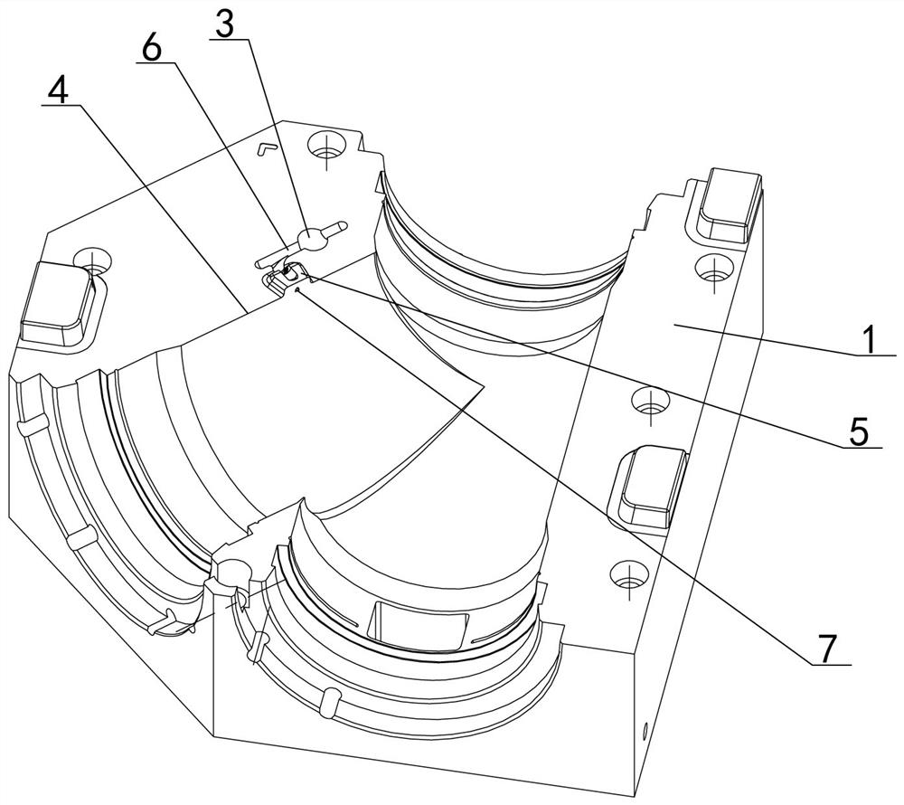
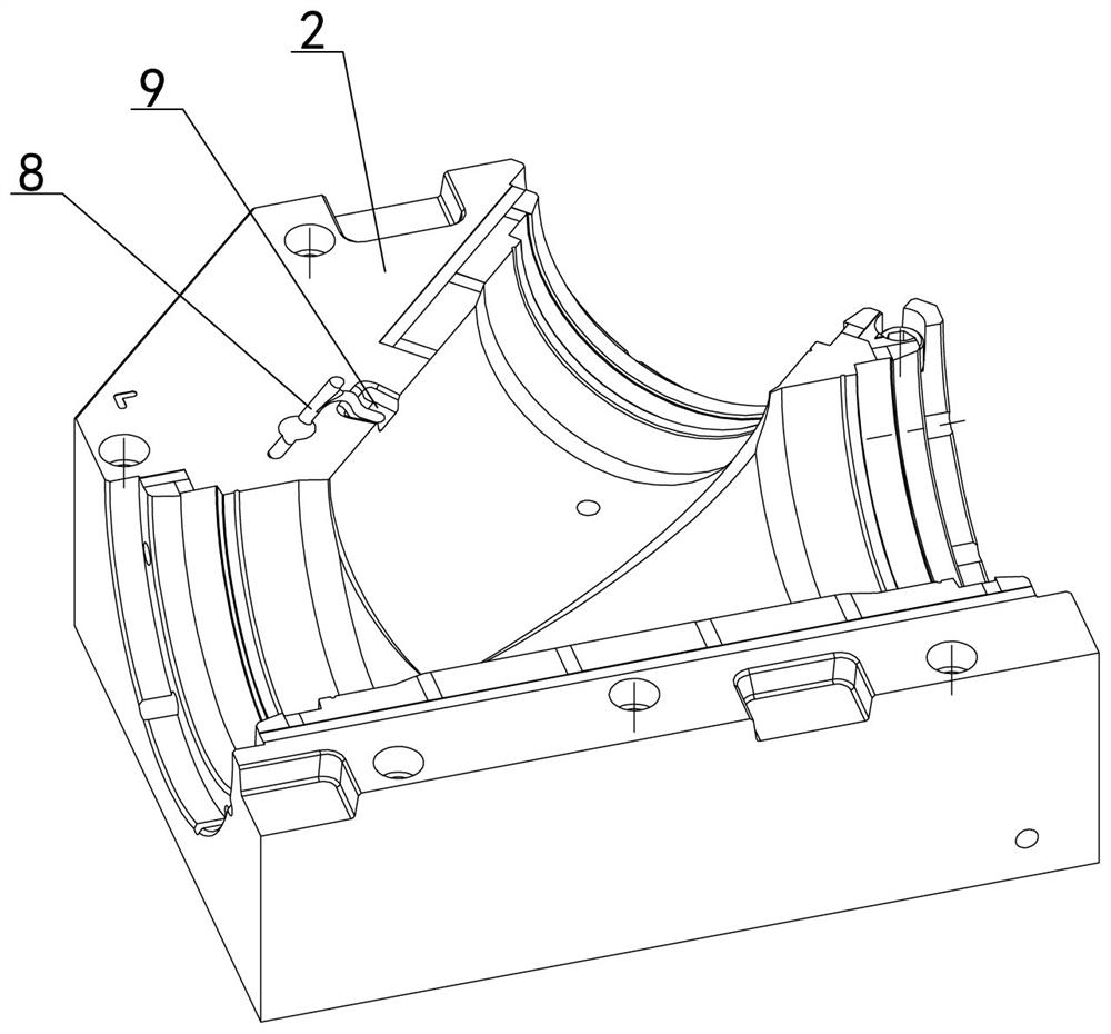
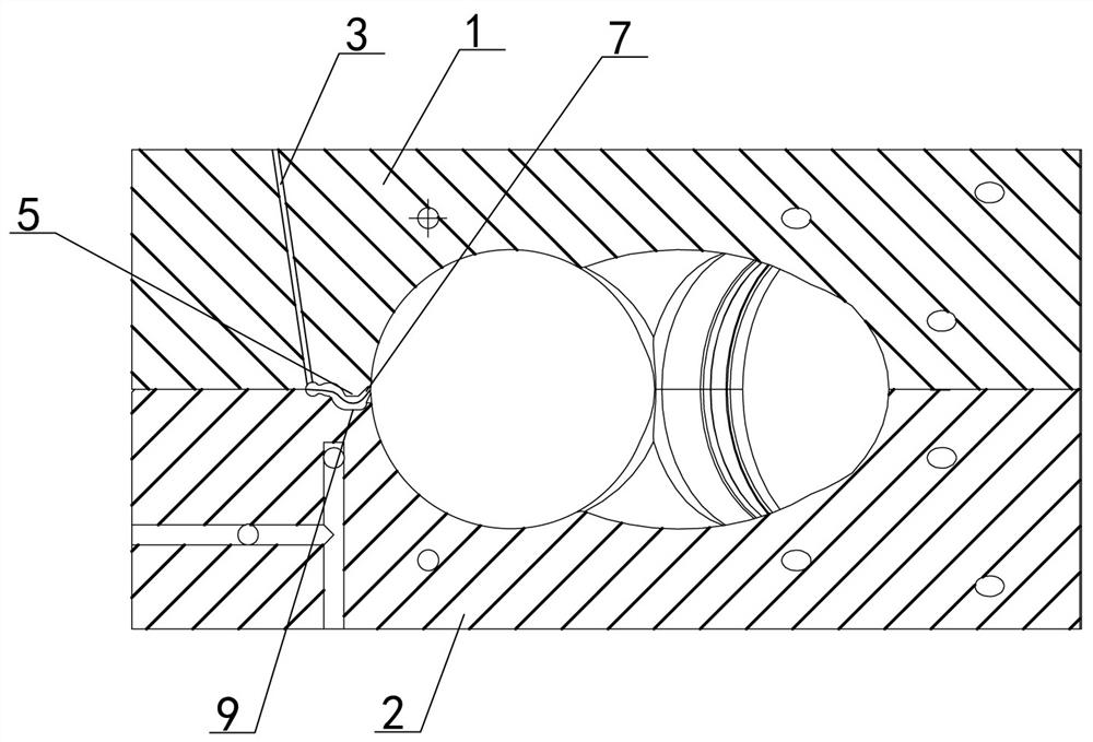
[0010] The invention relates to a plastic pipe fitting mold bump type latent gate, which comprises a mold cavity insert 1 and a core insert 2. A flow channel hole 3 is formed in the cavity insert 1. A bump 5 is set on the parting line 4 of the cavity insert, a cavity flow channel 6 is set between the bump 5 and the runner hole 3, a latent gate 7 is set in the bump, and the corresponding core insert 2 is set The core runner 8 and the groove 9, the bump 5 matches the groove 9, the cavity runner 6 matches the core runner 8, the latent gate 7 matches the cavity runner 6 and the core runner 8 connected. The main feature of this scheme is that a bump 5 is set on the parting line 4 of the cavity insert, and a latent gate 7 is set in the bump. After the plastic raw material enters, it flows evenly to both sides (cavity side and core side), and finally merges together. The joint is welded evenly, with less welding marks, beautiful appearance of the pipe fittings, and improved product ...


PUM


Abstract

The invention relates to a lug type tunnel gate for a plastic pipefitting die. The tunnel gate comprises a die cavity insert and a core insert. A runner hole is formed in the cavity insert. The tunnel gate is characterized in that a lug is arranged on a parting line of the cavity insert close to the runner hole, a cavity runner is formed between the lug and the runner hole, a tunnel gate is arranged in the lug, a core runner and a groove are formed in the corresponding core insert, the lug is matched with the groove, the cavity runner is matched with the core runner, and the tunnel gate communicates to the cavity runner (6) and the core runner. The tunnel gate is primarily characterized in that the lug is arranged on the parting line of the cavity insert, and the tunnel gate is arranged in the lug. The tunnel gate has the advantages that when a flue inlet sprue is located on the parting line of the die, a melted plastic raw material entering flow toward two sides (a cavity side and a core side) uniformly and then is gathered together, so that a joint is welded uniformly, the weld marks are few, the pipefitting is attractive in appearance and the product quality and grade are improved.

Description

technical field [0001] The invention relates to a convex block type latent gate of a plastic pipe fitting mold, which belongs to the field of injection molds. Background technique [0002] The injection mold is used to produce plastic pipe fittings. According to the product structure and shape analysis, the parting line of the plastic pipe fitting mold is set in the middle of the plastic pipe fittings, and the injection gate is set below the parting line. However, in actual production, since the injection gate is below the parting line, the molten plastic raw material flows into the mold cavity from both sides after being injected from the gate. As a result, the two strands of plastic raw material cannot reach the intersection position at the same time. A certain temperature difference will easily produce weld marks during welding, which will affect the appearance of the product. Contents of the invention [0003] The purpose of the present invention is to overcome the di...

Claims


Application Information

Patent Timeline
Patent Type & Authority Applications(China)
IPC IPC(8): B29C45/27
Inventor 张欢庆
Owner TAIZHOU HUANGYAN WEIDA PLASTIC MACHINERY
Why Eureka
Try Eureka