An emergency repair device for railway signaling equipment
A railway signal and equipment technology, applied in the field of emergency repair devices for railway signal equipment, can solve problems such as inability to erect cables, and achieve the effect of easy repair and processing
- Summary
- Abstract
- Description
- Claims
- Application Information
AI Technical Summary
Problems solved by technology
Method used
Image

Examples
specific Embodiment approach 1
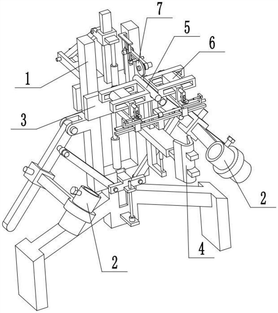
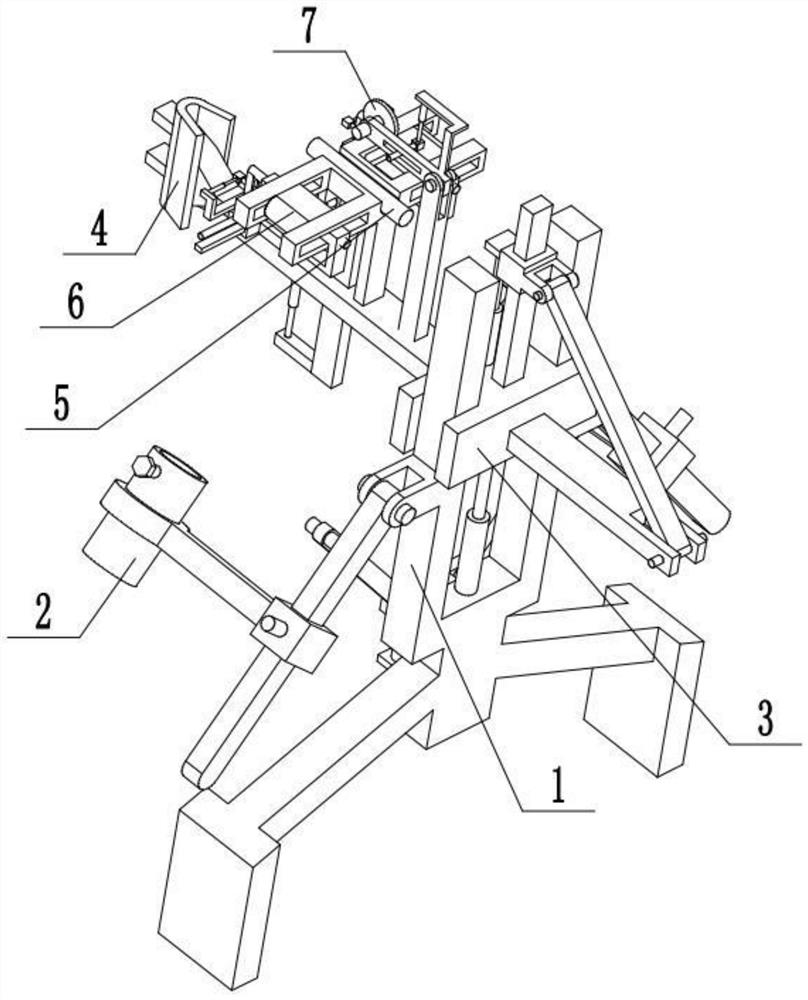
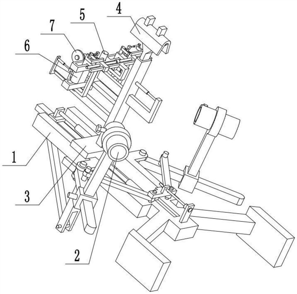
[0027] Combine below Figure 1-8 Description of this embodiment, an emergency repair device for railway signal equipment, including a U-shaped frame 1, a sleeve 2, an I-shaped block 3, a vertical rod 3-1, a sliding sleeve 3-2, a second electric push rod 3-3, Articulated arm 3-4, slide bar 3-5 and V-shaped plate 4, the two ends of described U-shaped frame 1 are respectively provided with a sleeve 2, and I-shaped block 3 is arranged on the middle part of U-shaped frame 1, and I-shaped The block 3 is fixedly connected to the vertical rod 3-1, the sliding sleeve 3-2 is movably connected to the vertical rod 3-1, the sliding sleeve 3-2 is fixedly connected to the telescopic end of the second electric push rod 3-3, and the second electric push rod The rod 3-3 is fixedly connected to the I-shaped block 3, and the two ends of the articulated arm 3-4 are respectively rotated to connect the sliding sleeve 3-2 and one end of the sliding rod 3-5, and the middle part of the sliding rod 3-5 ...
specific Embodiment approach 2
[0028] Combine below Figure 1-8 To illustrate this embodiment, the described emergency repair device for railway signal equipment also includes a push rod 5, a vertical frame 5-1 and a third electric push rod 5-2, and the push rod 5 is fixedly connected to the vertical frame 5-1. The vertical frame 5-1 is slidably connected to the slide bar 3-5, the vertical frame 5-1 is fixedly connected to the telescopic end of the third electric push rod 5-2, and the third electric push rod 5-2 is fixedly connected to the slide rod 3- 5 on. Pass the cable from the sleeve 2 on the left side around the upper end of the ejector rod 5, and pass it out from the sleeve 2 on the right side, adjust the damaged part of the cable to the upper end of the ejector rod 5, and pull the cable After tightening, the damaged part of the cable is protruded and erected from the upper end of the device, which is convenient for the staff to carry out targeted maintenance on the damaged part of the cable on the ...
specific Embodiment approach 3
[0029] Combine below Figure 1-8To illustrate this embodiment, the described emergency repair device for railway signal equipment also includes an I-shaped frame 5-3, a support plate 5-4 and a groove 5-5, and the I-shaped frame 5-3 is fixedly connected to the support plate 5- 4, the support plate 5-4 is fixedly connected to the slide bar 3-5, the vertical frame 5-1 is slidably connected to the I-shaped frame 5-3, and the middle part of the I-shaped frame 5-3 is provided with a groove 5-5, The push rod 5 is located in the groove 5-5. The cable passes through the sleeve 2 on the left side, enters the left end of the I-shaped frame 5-3, walks around the upper end of the push rod 5, passes through the right-hand end of the I-shaped frame 5-3, and then passes through the sleeve 2 on the right side. Out, the I-shaped frame 5-3 is set as an I-shaped, which is convenient to guide and limit the cables, and avoids the cables from moving back and forth substantially during the maintenan...
PUM
 Abstract
Description
Claims
Application Information
 - R&D
- Intellectual Property
- Life Sciences
- Materials
- Tech Scout
- Unparalleled Data Quality
- Higher Quality Content
- 60% Fewer Hallucinations
Browse by: Latest US Patents, China's latest patents, Technical Efficacy Thesaurus, Application Domain, Technology Topic, Popular Technical Reports.
© 2025 PatSnap. All rights reserved.Legal|Privacy policy|Modern Slavery Act Transparency Statement|Sitemap|About US| Contact US: help@patsnap.com