
Quick tightening device for through channel

A channel-through, fast technology, applied in the field of fast tightening devices for the channel, can solve the problems of cumbersome operation, time-consuming and labor-consuming, etc., and achieve the effect of shortening the operation time, convenient operation, and stabilizing the channel

Pending Publication Date: 2021-04-09
欧特美交通科技股份有限公司
View PDF2 Cites 0 Cited by
  • Summary
  • Abstract
  • Description
  • Claims
  • Application Information

AI Technical Summary

Problems solved by technology

[0003] In the existing rail vehicles, the tightening and fixing of the passageway is realized by manually pushing and pulling in place and then binding the tightening rope. The operation is cumbersome and requires the assistance of 2 or more personnel to complete it, which is time-consuming and labor-intensive. , for example: Chinese patent 201310364052.2 discloses a through-passage tightening rod assembly in the process of automobile transportation, including a positioning ring, a positioning seat, two fixing cards and a tightening rod, the positioning ring is fixed on the screw frame of the vehicle passage, and the positioning seat It is fixed on the connection frame of the vehicle through passage; the tightening rod is composed of a turning handle and two pulling rods, the two ends of the turning handle are provided with internal threads, one end of the two pulling rods is provided with a hook, and the other end is provided with external threads , the turning handle and the two pull rods are connected by threads, and the distance between the two pull rods increases or decreases through the cooperation of the internal and external threads; the two fixing cards are fixed in the middle of the screw frame of the vehicle through passage, and the two fixing cards are set up and down. And the distance between the two is greater than or equal to the overall length of the handle

Method used


Image

  • Quick tightening device for through channel
  • Quick tightening device for through channel
  • Quick tightening device for through channel

Examples


Embodiment 1

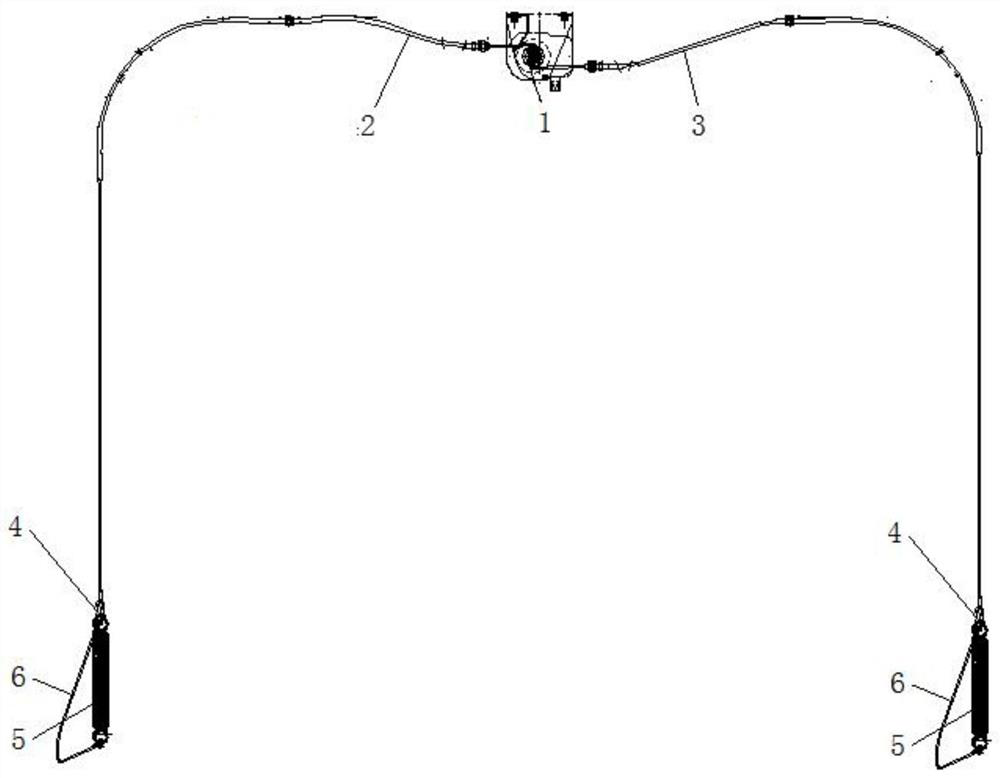
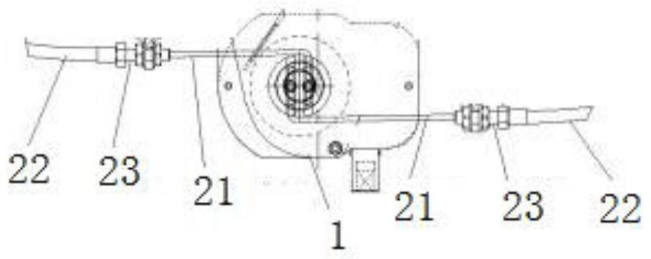
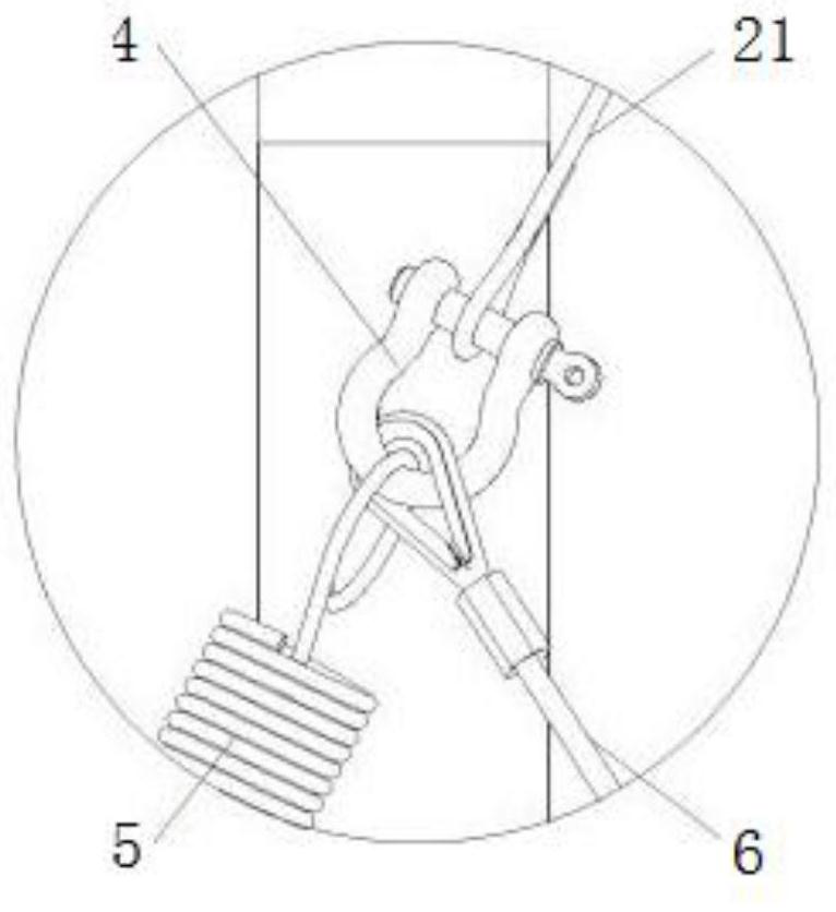
[0019] The main structure of the quick-tightening device for through passages involved in this embodiment includes a tightener 1, a left rope 2, a right rope 3, a clasp 4, a damper 5 and a limit rope 6; 2 is connected with one end of the right rope 3, the other ends of the left rope 2 and the right rope 3 are respectively connected with the clasp 4, and the clasp 4 is connected with the damper 5 and the limit rope 6; the tightener 1 is connected with the fixed side frame 100 Connection; there are two coaxial grooved wheels 11 parallel to each other in the tightener 1, and the tightener 1 is also provided with a mounting hole 12 and a torque input interface 13; the main structure of the left rope 2 and the right rope 3 Same, they all include a pull cord 21, a protective sleeve 22 and an installation shaft 23;

[0020] When using the through channel with a new type of fast tightening mechanism involved in this embodiment, the tightener 1 is connected to the fixed side frame body...


PUM


Abstract

The invention belongs to the technical field of rail transit equipment, and relates to a quick tightening device for a through passage; the main structure of the quick tightening device comprises a tightener, a left rope, a right rope, a snap ring, a damper and a limiting rope; the tightener is connected with one end of the left rope and one end of the right rope respectively, and the other ends of the left rope and the right rope are connected with the snap ring respectively; the snap ring is connected with the damper and the limiting rope, is located in the through channel at the joint of two carriages, can adapt to position changes generated by relative movement between vehicles during train coupling based on the flexibility characteristic of the snap ring, can rapidly and reliably fold the through channel during unpacking, greatly shortens the operation time, relieves the labor intensity of operators, and improves the operation efficiency; the quick tightening device is simple in structure and convenient to operate; the tightener drives the pull rope to tighten and release the through channel, and the requirement for quick tightening and releasing of the through channel is met; meanwhile, the effect of stabilizing the through channel during unlocking is achieved, and technical support is provided for intelligent marshalling of trains.

Description

Technical field: [0001] The invention belongs to the technical field of rail transit equipment, and in particular relates to a quick tightening device for a passageway, which can realize fast and reliable retraction of the passageway during decoupling, shorten operation time, reduce labor intensity, and improve operation efficiency. Background technique: [0002] The through passage is an internal passage for passengers to walk freely from one compartment of the vehicle to another and make passengers feel safe and comfortable. The tightening device is one of the important components of the through passage, which is used to retract, fix and release the through passage . [0003] In the existing rail vehicles, the tightening and fixing of the passageway is realized by manually pushing and pulling in place and then binding the tightening rope. The operation is cumbersome and requires the assistance of 2 or more personnel to complete it, which is time-consuming and labor-intensi...

Claims


Application Information

Patent Timeline
Patent Type & Authority Applications(China)
IPC IPC(8): B61D17/22
CPCB61D17/22
Inventor 刘正发李送军聂长海蔡亦文
Owner 欧特美交通科技股份有限公司
Learn More