A concrete mixing device
A mixing device and concrete technology, which is applied to cement mixing devices, clay preparation devices, chemical instruments and methods, etc., can solve the problems of wasting manpower and time, and the quantification of materials that cannot be added, so as to save time, avoid the weighing process, Reduce the effect of cleaning work
- Summary
- Abstract
- Description
- Claims
- Application Information
AI Technical Summary
Problems solved by technology
Method used
Image

Examples
Embodiment 1
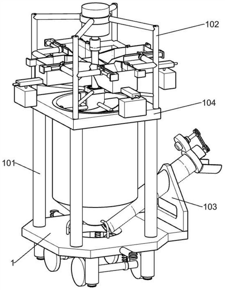
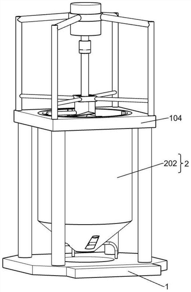
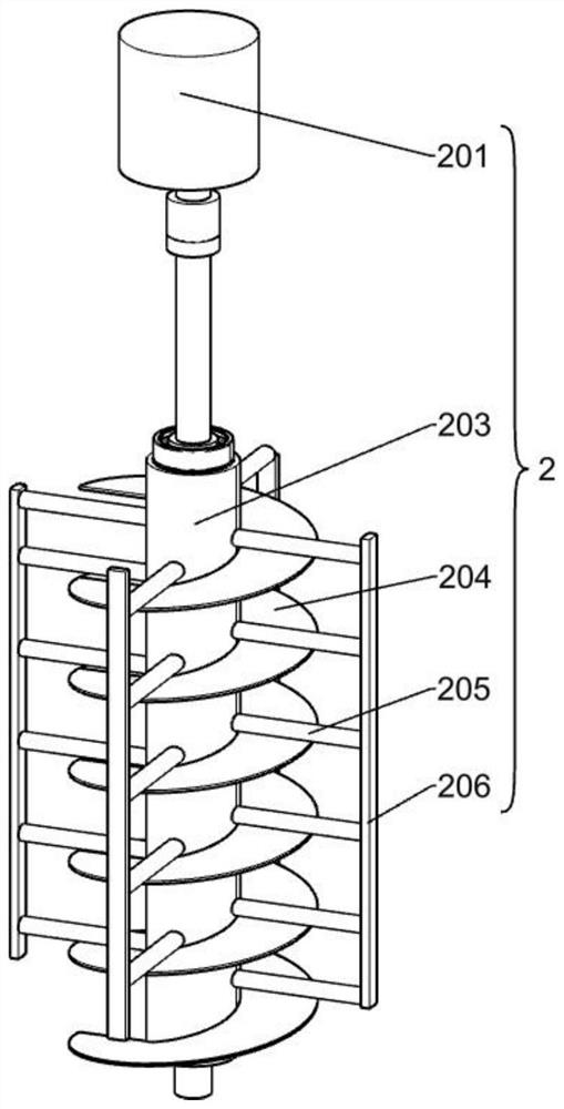
[0071] A concrete mixing device, such as Figure 1-9 As shown, it includes: base 1, pillar 101, upper bracket 102, side bracket 103 and stirring mechanism 2, base 1 is square, four corners of base 1 are fixedly provided with four pillars 101, support plate 104 is square, and there is a circle in the middle shaped opening, the support plate 104 is fixed on the four pillars 101, the upper bracket 102 is fixed on the four corners of the support plate 104, the side bracket 103 is fixed on one side of the base 1, and the stirring mechanism 2 is fixed on the upper bracket 102. Mechanism 2 includes a first motor 201, a mixing drum 202, a first helical shaft 203, a first helical blade 204, a first connecting rod 205 and a scraper 206, the first motor 201 is fixed on the upper bracket 102, and the agitating drum 202 The lower end is fixed on the base 1 through a bracket, the upper end of the mixing drum 202 is fixedly connected with the support plate 104, the output shaft of the first ...
Embodiment 2
[0074] On the basis of Example 1, such as Figure 4-6 As shown, a blanking mechanism 3a is also included. The blanking mechanism 3a includes a feeding box 301, a horizontal support 3011, a second cylinder 308 and a buckle 309. There are four feeding boxes 301, which are evenly distributed in four directions. One end of the horizontal bracket 3011 is fixedly connected to the upper bracket 102, and the other end is slidingly connected with the feeding box 301. Both sides of each feeding box 301 are symmetrically provided with horizontal brackets 3011 distributed in four directions, and the second cylinder 308 is fixed. Set on the feeding box 301, each side of each feeding box 301 is provided with a second cylinder 308, the telescopic rod of the second cylinder 308 is fixedly connected with the horizontal bracket 3011, and one end of the buckle 309 is fixed on the horizontal bracket 3011 , and the other end rests on the feeding box 301 , and both sides of each feeding box 301 are...
Embodiment 3
[0079] On the basis of Example 2, such as Figure 7-9 As shown, a discharge mechanism 4 is also included, and the discharge mechanism 4 includes a discharge cylinder 401, a discharge plate 402, a second motor 403, a motor bracket 4031, a first runner 404, a belt 405, and a second runner 406 , the second helical shaft 407, the fixed block 4071 and the second helical blade 408, the discharge cylinder 401 is fixedly connected to the bottom of the side of the mixing cylinder 202, pierced through the side bracket 103, and the discharge plate 402 is fixedly connected to the outlet of the discharge cylinder 401 The motor bracket is fixedly set on the discharge cylinder 401, the second motor 403 is fixed on the motor bracket 4031, located above the discharge cylinder 401, the second screw shaft 407 is rotatably installed on the wall of the discharge cylinder 401, and the fixed block 4071 is fixed on the outlet of the discharge cylinder 401, above the discharge plate 402, the second sc...
PUM
 Abstract
Description
Claims
Application Information
 - R&D
- Intellectual Property
- Life Sciences
- Materials
- Tech Scout
- Unparalleled Data Quality
- Higher Quality Content
- 60% Fewer Hallucinations
Browse by: Latest US Patents, China's latest patents, Technical Efficacy Thesaurus, Application Domain, Technology Topic, Popular Technical Reports.
© 2025 PatSnap. All rights reserved.Legal|Privacy policy|Modern Slavery Act Transparency Statement|Sitemap|About US| Contact US: help@patsnap.com