A positioning and fixing device for plate processing for houses

A fixing device and plate processing technology, which is applied in the direction of positioning devices, metal processing equipment, metal processing machinery parts, etc., can solve the problems of reducing processing efficiency, destroying the processing surface, unfavorable continuity, etc., achieving shortened positioning time and weakened friction performance , Reduce the effect of manual cleaning

Active Publication Date: 2022-03-25
青岛亿联建设集团股份有限公司
View PDF10 Cites 0 Cited by
  • Summary
  • Abstract
  • Description
  • Claims
  • Application Information

AI Technical Summary

Problems solved by technology

[0002] House panels are commonly used structural materials. During the processing and forming stage, the panels need to be bent, cut, punched, etc., especially for some panels that need to be assembled, which require relatively high processing accuracy. Therefore, it is necessary to Precise positioning of the position of the plate. In the existing market, two-way positioning is mostly used for the plate, which cannot guarantee the accuracy of the plate during processing. The plate is easily affected by external forces and moves, damaging the processing surface. Some processing equipment performs multiple positioning through the plate chuck. The shape and size of the boards used for housing will not be fixed. When processing some arc surfaces and inclined surfaces, the plate chucks often cannot complete accurate positioning, and the surface positioning becomes line positioning or even point positioning. It is easy to move under force, and does not Good for processing
In addition, in the process of processing, it is easy to generate residues. If chips are not removed in time and directly piled up on the surface of the equipment, it is easy to affect the processing accuracy during subsequent processing. To ensure safety, stop cutting and discharge will reduce processing efficiency, which is not conducive to continuous mass production. Although some equipment fully uses motor-assisted feed, which reduces the positioning time, it is not conducive to the accuracy of positioning

Method used


Image

  • A positioning and fixing device for plate processing for houses
  • A positioning and fixing device for plate processing for houses
  • A positioning and fixing device for plate processing for houses

Examples


Embodiment Construction

[0029] The following will clearly and completely describe the technical solutions in the embodiments of the present invention with reference to the accompanying drawings in the embodiments of the present invention. Obviously, the described embodiments are only some, not all, embodiments of the present invention. Based on the embodiments of the present invention, all other embodiments obtained by persons of ordinary skill in the art without making creative efforts belong to the protection scope of the present invention.

[0030] The present invention provides following technical scheme:

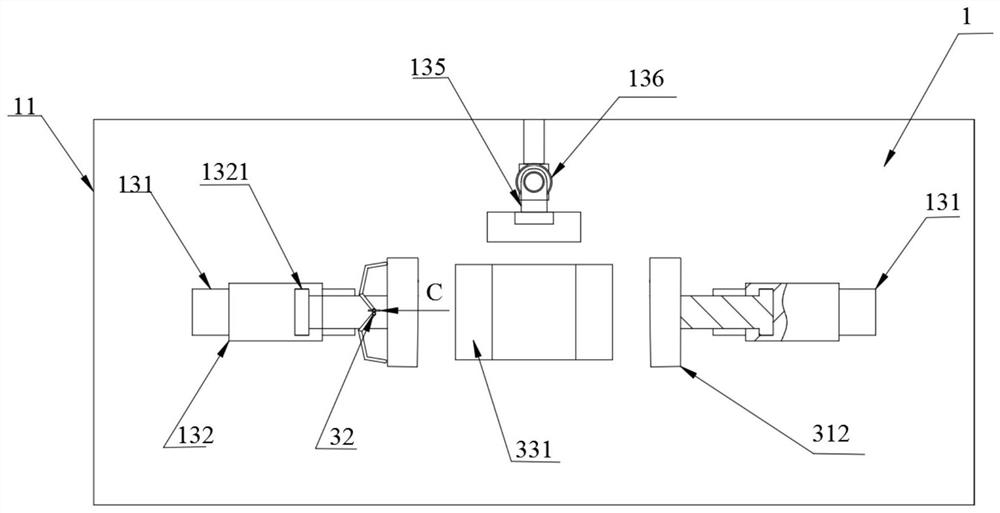
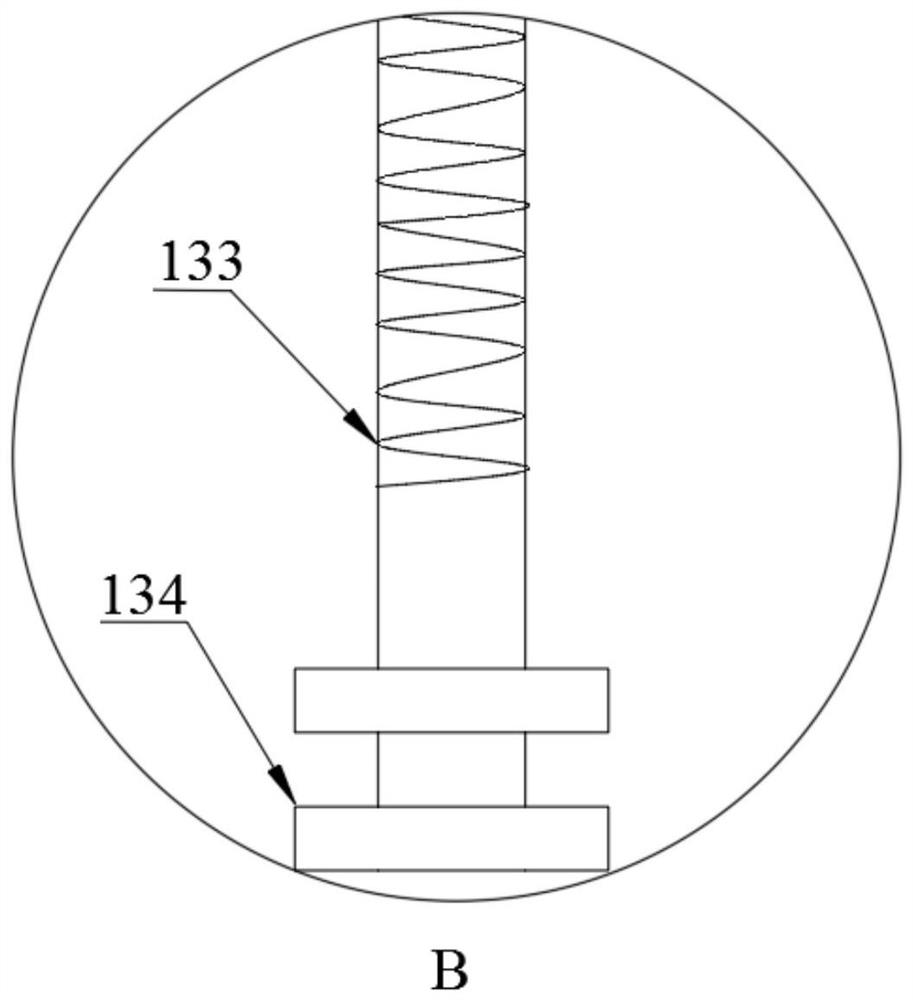
[0031] Such as Figure 1~6 As shown, a plate processing positioning and fixing device for a house includes a frame assembly 1, a power transmission device 2 and a clamping device 3. The power transmission device 2 and the frame assembly 1 are tightly connected, and the frame assembly 1 and the clamping device 3 are tightly connected. The power transmission device 2 is located under the frame ...


PUM


Abstract

The invention discloses a plate processing, positioning and fixing device for a house, which includes a frame assembly, a power transmission device and a clamping device, the power transmission device and the frame Below the frame assembly, the clamping device includes a positioning chuck assembly, a movable chuck assembly and a baffle assembly, the positioning chuck assembly and the movable chuck assembly are movably connected, and the baffle assembly is movably connected to the frame assembly; the middle of the first chuck The concave surface is the clamping surface, the two ends of the first chuck are provided with clamping planes, the convex surface of the second chuck is the clamping surface, and the third chuck is a flat splint; the power transmission device includes a screw, and the screw has two The end passes through the inner ring of the bearing, and the screw and the bearing are rotatably connected.

Description

technical field [0001] The invention relates to the technical field of panel processing and fixing, in particular to a panel processing, positioning and fixing device for a house. Background technique [0002] House panels are commonly used structural materials. During the processing and forming stage, the panels need to be bent, cut, punched, etc., especially for some panels that need to be assembled, which require relatively high processing accuracy. Therefore, it is necessary to Precise positioning of the position of the plate. In the existing market, two-way positioning is mostly used for the plate, which cannot guarantee the accuracy of the plate during processing. The plate is easily affected by external forces and moves, damaging the processing surface. Some processing equipment performs multiple positioning through the plate chuck. The shape and size of the boards used for housing will not be fixed. When processing some arc surfaces and inclined surfaces, the plate c...

Claims


Application Information

Patent Timeline
Patent Type & Authority Patents(China)
IPC IPC(8): B23Q3/00B23Q11/12B23Q11/00
CPCB23Q3/00B23Q11/126B23Q11/005
Inventor 王学芹丁波张鹏李璟
Owner 青岛亿联建设集团股份有限公司
Why Eureka
Try Eureka