
A monitoring device for intelligent safety production

A monitoring device and safety production technology, which is applied to the parts of color TVs, parts of TV systems, TVs, etc., can solve the problems of low practicability, invisible observation, time-consuming and labor-intensive, etc., and achieve high practicability and easy observation. , reduce the effect of occlusion

Inactive Publication Date: 2022-04-08
CHINA RAILWAY NO 5 ENG GRP
View PDF6 Cites 0 Cited by
  • Summary
  • Abstract
  • Description
  • Claims
  • Application Information

AI Technical Summary

Problems solved by technology

[0002] With the development of science and technology, the application of intelligent production is more and more extensive, and in the process of intelligent production, manpower is saved, and the on-site equipment needs to be observed by the user when it is running, so as to reduce the damage caused by equipment failure. However, when a large number of machines are in operation, it is time-consuming and labor-intensive to rely on human walking to observe the operation of the equipment. Therefore, the use of monitoring devices to observe is more and more widely used, and the existing monitoring devices include the camera body. Install the camera body at a fixed position. If there is an obstacle in front, the camera body will not be able to observe some areas, which is not convenient for users to observe and has low practicability. In addition, other existing patented technologies such as CN203513483U simply use three The positioning adjustment of the camera is carried out by motor and lead screw drive technology in three dimensions, but the camera is in an extreme position such as the end position of the three dimensions of xyz at the same time. At this time, if the camera is heavy, the center of gravity of the suspension or support of the camera will be different. Stablize

Method used


Image

  • A monitoring device for intelligent safety production
  • A monitoring device for intelligent safety production
  • A monitoring device for intelligent safety production

Examples


Embodiment

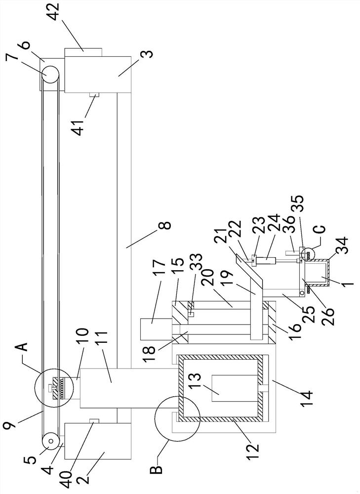
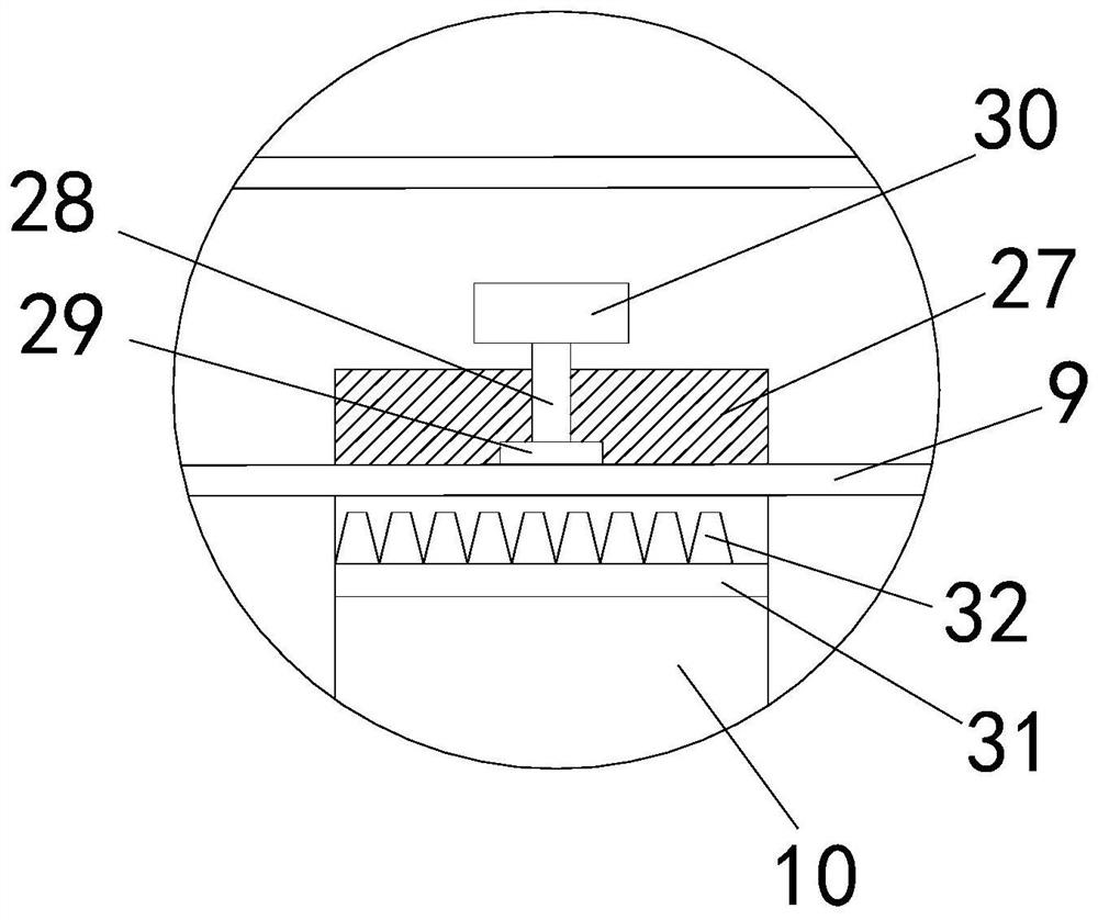
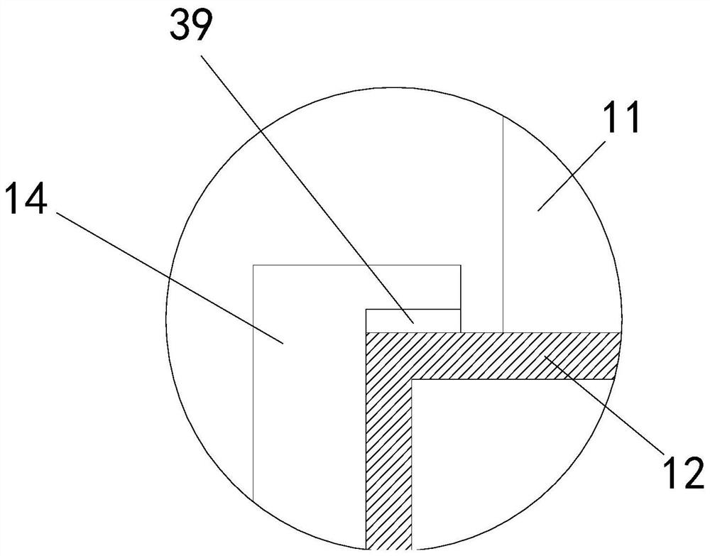
[0025] see Figure 1-7 , a monitoring device for intelligent and safe production, comprising a camera body 1, a first support frame 2 and a second support frame 3, the top of the first support frame 2 is fixedly connected with a raised plate 4, the A rotating wheel 5 is hinged on the upper part of the front end of the height-increasing board 4 , a bidirectional first motor 6 is installed on the top of the second support frame 3 , and a driving wheel 7 is fixedly connected to the output shaft end of the first motor 6 . A beam 8 is fixedly connected between the opposite ends of the support frame 2 and the second support frame 3, the driving wheel 7 and the runner 5 are connected by a connecting belt 9, and the middle part of the connecting belt 9 is detachably connected with an adapter plate 10 , a mass block is arranged on the top of the belt body of the connecting belt 9, wherein the initial positions of the adapter plate 10 and the mass block are respectively located at both ...


PUM


Abstract

The invention relates to the technical field of intelligent production, in particular to a monitoring device for intelligent and safe production, comprising a first support frame, a second support frame, a heightening plate, a runner, a first motor, a driving wheel, a beam, a connection The belt and the adapter plate, the bottom end of the adapter plate is fixedly connected with a vertical plate, the bottom end of the vertical plate is fixedly connected with a support box, the bottom end of the inner wall of the support box is installed with a second motor, and the output end of the second motor is fixedly connected with a rotating box, which rotates The top of the inner wall of the box is in contact with the top of the support box, an upper plate is fixedly connected to the upper part of the right end of the rotating box, a lower plate is fixedly connected to the lower part of the right end of the rotating box, a third motor is installed on the left part of the top top of the upper plate, and a third motor is fixedly connected to the output shaft end of the third motor. A screw, the middle part of the first screw is connected with a moving plate by a thread, the right part of the bottom end of the upper plate is fixedly connected to a limit plate, and the right end of the moving plate passes through the middle of the limit plate from the left end of the limit plate; it reduces the blocking of the camera body by obstacles , which is convenient for users to observe and has high practicability.

Description

technical field [0001] The invention relates to the technical field of intelligent production, in particular to a monitoring device for intelligent safety production. Background technique [0002] With the development of science and technology, the application of intelligent production is more and more extensive, and in the process of intelligent production, manpower is saved, and the on-site equipment needs to be observed by the user when the equipment is running, so as to reduce the damage caused by the equipment failure. For a large number of machines in operation, it is time-consuming and laborious to observe the operation of the equipment by human walking. Therefore, the use of monitoring devices to observe the application is more and more widely used, and the existing monitoring devices include the camera body. The camera body is installed in a fixed position. If there is an obstacle in front, the camera body will not be able to observe part of the area, which is incon...

Claims


Application Information

Patent Timeline
Patent Type & Authority Patents(China)
IPC IPC(8): F16M13/02F16M11/12F16M11/10F16M11/08F16M11/18H04N5/225H04N7/18
CPCF16M13/02F16M11/045F16M11/121F16M11/10F16M11/08F16M11/18H04N7/18H04N23/50
Inventor 武建华
Owner CHINA RAILWAY NO 5 ENG GRP
Learn More