Eureka AIR delivers breakthrough ideas for toughest innovation challenges, trusted by R&D personnel around the world.

Display device and backlight module

A display device and backlight module technology, which is applied in optics, nonlinear optics, instruments, etc., can solve the problems of subjective uneven lighting, insufficient light emission conditions and mixed light, and the inability to set light bars, etc., to meet the aesthetic requirements effect of demand

Pending Publication Date: 2021-03-30
HISENSE VISUAL TECH CO LTD
View PDF10 Cites 1 Cited by
  • Summary
  • Abstract
  • Description
  • Claims
  • Application Information

AI Technical Summary

Problems solved by technology

However, with people's pursuit of beautiful and novel appearance of display devices, the backplane of the backlight module tends to be made into a non-planar shape, which makes it impossible for the light bars in the backlight module to be arranged on the backplane with a special shape. Even if it can be set on such a backplane, it will still cause subjective uneven lighting due to light exit conditions and insufficient light mixing

Method used


Image

  • Display device and backlight module
  • Display device and backlight module
  • Display device and backlight module

Examples


Embodiment Construction

[0038] In order to make the objectives, technical solutions and advantages of the present invention clearer, the present invention will be further described in detail below with reference to the accompanying drawings. Obviously, the described embodiments are only a part of the embodiments of the present invention, not all of the embodiments. Based on the embodiments of the present invention, all other embodiments obtained by persons of ordinary skill in the art without creative efforts shall fall within the protection scope of the present invention.

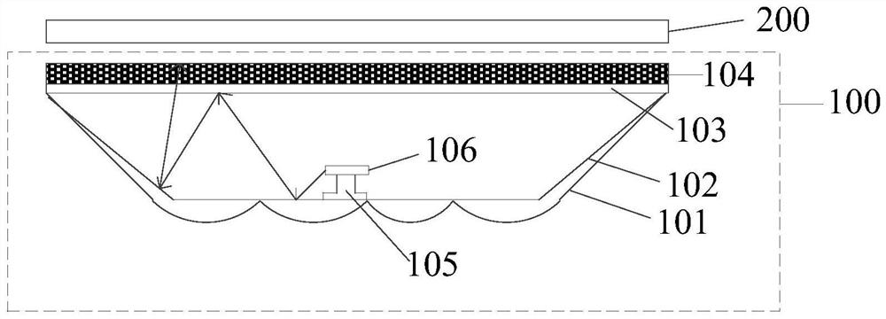
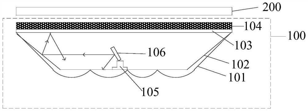
[0039] In a first aspect, the present invention provides a display device. Please refer to figure 1 , is a schematic cross-sectional structure diagram of a display device provided by an embodiment of the present invention. like figure 1 As shown, the display device includes a backlight module 100 and a display panel 200 located on the light-emitting side of the backlight module 100 . The backlight module 100 includes: a backpl...


PUM

PropertyMeasurementUnit
reflectanceaaaaaaaaaa

Abstract

The invention provides a display device and a backlight module, the display device comprises the backlight module and a display panel located on the light emitting side of the backlight module. The backlight module comprises a back plate, a reflection plate located on the surface of the back plate, a diffusion plate located on the side, away from the back plate, of the reflection plate, and a partial reflection and partial transmission layer located on the surface of the side, facing the reflection plate, of the diffusion plate; a support fixed on the reflecting plate, and a light bar installed on the support. The reflecting plate and the diffusion plate form a hollow cavity; the bracket is used for supporting the light bar, so that set distances exist between the light bar and the reflecting plate and between the light bar and part of reflecting part transmitting layer; and the reflecting plate and part of reflecting part transmitting layer are used for reflecting part of emergent light of the light bar outwards from one side of the diffusion plate after limited times of reflection in the cavity. According to the structure, light rays are reflected for multiple times in the cavity, the light rays emitted by the light bar can be fully mixed, the reflected light uniformly enters the diffusion plate from the partially-reflecting and partially-transmitting layer, and finally uniform backlight is provided for the display device.

Description

technical field [0001] The invention relates to the technical field of display, in particular to a display device and a backlight module. Background technique [0002] A liquid crystal display device is a main display device on the market. It includes a backlight module and a liquid crystal display panel. The liquid crystal display panel itself cannot emit light, and the backlight module needs to provide uniform surface illumination. [0003] In the traditional direct type backlight module, a light bar is included, and the light bar is arranged on the back panel of the backlight module. The surface forms a more uniform light output. However, with the pursuit of beautiful appearance and novelty of display devices, the backplane of the backlight module is more inclined to be made into a non-planar shape, which makes it impossible for the light bar in the backlight module to be arranged on the backplane with a special shape. Even if it can be installed on such a backplane, th...

Claims


Application Information

Patent Timeline
Patent Type & Authority Applications(China)
IPC IPC(8): G02F1/13357
CPCG02F1/133605G02F1/133606G02F1/133608G02F1/133611
Inventor 陈超丛晓东鞠磊磊
Owner HISENSE VISUAL TECH CO LTD
Why Eureka
Eureka Blog
Learn More