


Quick Research
Generate reliable direction feasibility study reports for your R&D in just a few steps.

Technical Q&A
Discover and master advanced knowledge NOW. Basics, ideas, possibilities, all at once.

Find Solutions
As an expert in R&D theories, this can generate solutions to your technical problems instantly.

Evaluate Feasibility
Analyze your overall solution with one click, know your potential R&D risks in advance.

Monitor Landscape
Get weekly tech updates, stay abreast of the latest tech innovations and key insights.
folding support feet
A supporting foot, foldable technology, applied in the direction of casters, supporting machines, machines/stands, etc., can solve the problems of easily broken legs, large supporting base, inconvenient transport and carrying, etc., and achieves high practical value and small volume. Effect
- Summary
- Abstract
- Description
- Claims
- Application Information
AI Technical Summary
Problems solved by technology
Method used
Image

Examples
Embodiment 1
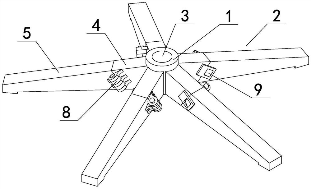
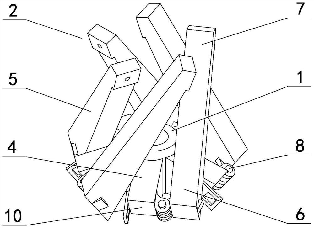
[0032] exist figure 1 figure 2 In the illustrated embodiment 1, a foldable support leg includes a base body 1 and a support leg 2 radially arranged on the outer periphery of the base body. The base body is a cylindrical structure, and the outer side of the base body is a cylindrical surface. There is a mounting hole 3 in the middle, and the said feet are 5, which are evenly arranged on the outer side of the base body and inclined downward, and the angle between the feet and the horizontal plane is 8-15 degrees; the cross-section of the feet in this embodiment is rectangular, The angle between the upper surface of the leg and the horizontal plane is 15 degrees, the angle between the lower surface of the leg and the horizontal plane is 8 degrees, and the angle between the center line of the leg and the horizontal plane is between 8-15 degrees; the legs are two. segment structure, including fixed segment 4 and folded segment 5 (see Figure 7 ), the length of the center line of...
Embodiment 2
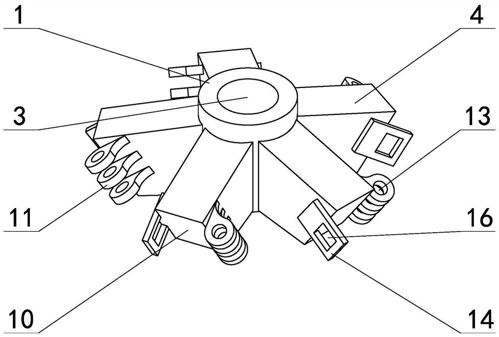
[0037] The folding support foot of Example 2 is further provided with an anti-folding mechanism of the foot, and the anti-folding mechanism includes an anti-folding sleeve embedded in the supporting foot, and the anti-folding sleeve includes an upper sleeve arranged in the fixed section. 17 and the lower sleeve 18 arranged in the folded section (see Figure 8 Figure 9 ), the upper casing and the lower casing are steel pipes or carbon fiber pipes with the same specifications, the upper casing and the lower casing are coaxially arranged and located at the lower part of the cross section of the legs, and the end of the lower casing away from the docking plane is connected with a thread The hole 19 is connected, and the inner diameter of the threading hole is smaller than the inner diameter of the lower sleeve. The threading hole in this embodiment is L-shaped and is composed of an L-shaped elbow preset in the leg. The opening of the threading hole at one end of the threading hol...
Embodiment 3
[0040] The number of legs in Example 3 is 4, the outer side of the base is four sides of a regular quadrilateral corresponding to the number of legs, each leg is arranged on one side of the regular quadrilateral, and the lower side of the grounding end of the leg is provided with a roller 24, the described The rollers are secured to the ground terminal by means of bolts 25 (see Figure 10 ). The foldable support foot is also provided with a strengthening mechanism, which includes a correspondingly set retractable pull rod 26 on the underside of each support foot (see Figure 11 ), one end of the retractable rod is connected to the grounding end of the foot (see Figure 13 ), the other end of the telescopic rod is rotatably connected to the ring 27 below the installation hole, when the reinforcing mechanism is removed and folded, the telescopic rod shrinks and rotates around the ring. The retractable pull rod is formed by connecting two pull bars 28. The pull bar is composed ...
PUM
 Abstract
Description
Claims
Application Information
 - R&D Engineer
- R&D Manager
- IP Professional
- Industry Leading Data Capabilities
- Powerful AI technology
- Patent DNA Extraction
Browse by: Latest US Patents, China's latest patents, Technical Efficacy Thesaurus, Application Domain, Technology Topic, Popular Technical Reports.
© 2024 PatSnap. All rights reserved.Legal|Privacy policy|Modern Slavery Act Transparency Statement|Sitemap|About US| Contact US: help@patsnap.com