Wheel hub motor

A technology for in-wheel motors and motor shafts, which is applied in the directions of electromechanical devices, electrical components, and electric components, can solve the problems of reducing motor life, waste of resources, and difficulty in heat, and achieves the improvement of service life, reduction of waste of resources, and reduction of maintenance costs. Effect

Pending Publication Date: 2021-03-26
深圳市前海胡桃科技有限公司
View PDF31 Cites 0 Cited by
  • Summary
  • Abstract
  • Description
  • Claims
  • Application Information

AI Technical Summary

Problems solved by technology

[0003] 1) Usually the life of the motor is longer than that of the tire. When using a scooter, the tire is easy to wear. It is difficult to replace them individually. At this time, the entire in-wheel motor needs to be returned to the factory to refill the tires or be scrapped. Returning to the factory to refill the tires will undoubtedly greatly increase the maintenance cost of the user, and scrapping will cause serious waste of resources;
[0004] 2) Since the motor is wrapped by tires with poor thermal conductivity, the heat generated by the motor during operation is difficult to dissipate through the tires in time
The heat accumulated inside the motor will cause a certain degree of damage to the magnets, enameled wires, and components on the PCB inside the motor, greatly reducing the life of the motor

Method used


Image

  • Wheel hub motor
  • Wheel hub motor
  • Wheel hub motor

Examples


Embodiment 1

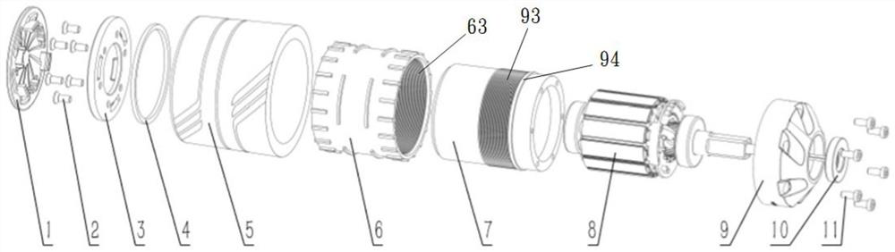
[0036] This embodiment provides a hub motor. see Figure 1 to Figure 5 , the hub motor includes a motor and a tire. The motor includes a rotor assembly, the tire includes an inner core 6 and a tire skin 5 covering the outside of the inner core 6, the inner core 6 has a fastening portion; Matching engaging part; the inner core 6 is sheathed on the rotor assembly, and the engaging part fits with the engaging part so that the inner core 6 can be driven when the rotor assembly rotates synchronous rotation; the hub motor also includes a gland 3 fixed on the left end surface of the rotor assembly, and the right side of the gland 3 presses against the left end surface of the inner core 6 .

[0037] see figure 2 and image 3 , the inner core 6 of the tire is a hollow cylindrical structure, and the tire skin 5 and the inner core 6 are directly casted.

[0038] The motor also includes a stator assembly 8, a motor shaft 12, a left side bearing 14, a right side bearing 15 and a moto...

Embodiment 2

[0049] This embodiment provides a hub motor. The difference from the first embodiment is only that the gland 3 and the inner core 6 are integrated. Compared with Embodiment 1, in the process of replacing the tire, after the first screw 2 fixing the gland 3 is loosened, there is no need to store the gland 3 additionally, which reduces the risk of parts loss .

Embodiment 3

[0051] This embodiment provides a hub motor. It differs from Embodiment 1 in that, see Figure 6 and Figure 7 , there is no protruding ring on the outer surface of the inner core 6, and the engaging portion is a plurality of protrusions 91 arranged on the left end surface of the end cap 9; the engaging portion is arranged on the inner There are a plurality of depressions 61 on the right end surface of the core 6; the inner core 6 is sleeved on the cylinder shell 7, and the plurality of protrusions 91 are embedded in the plurality of depressions 61 one by one. In this embodiment, the left end surface of the end cap 9 is provided with 6 protrusions 91 distributed at equal phase angle intervals, and the right end surface of the inner core 6 is provided with 6 depressions distributed at equal phase angle intervals. 61, so that the inner core 6 can be fixed to the rotor assembly by aligning the plurality of depressions 61 with the plurality of protrusions 91 respectively, so as ...


PUM


Abstract

The invention discloses a wheel hub motor, which comprises a motor and a tire, the motor comprises a rotor assembly, the tire comprises an inner core and a tire skin coating the outer side of the inner core, and the inner core is provided with a buckling part; the rotor assembly is provided with a clamping part matched with the buckling part; the inner core sleeves the rotor assembly, and the buckling part is embedded with the clamping part, so that the inner core can be driven to rotate synchronously when the rotor assembly rotates; the wheel hub motor also comprises a gland fixed on the leftside end surface of the rotor assembly, and the right side surface of the gland presses the left side end surface of the inner core. When the tire needs to be replaced due to the fact that the tire skin is abraded and cannot be used, the gland can be separated fromthe rotor assembly firstly, then the inner core is pulled out of the rotor assembly, and the tire and the motor can be separated rapidly. Therefore, independent replacement of the tire is achieved, resource waste is reduced, and maintenance cost is reduced.

Description

technical field [0001] The present invention relates to the technical field of motors, in particular to electric skateboards, and more specifically to a wheel hub motor. Background technique [0002] At present, the tires in the hub motors used in electric skateboards on the market are directly molded with the rotor housing of the motor, which leads to at least the following two disadvantages: [0003] 1) Usually the life of the motor is longer than that of the tire. When using a scooter, the tire is easy to wear. It is difficult to replace them individually. At this time, the entire in-wheel motor needs to be returned to the factory to refill the tires or be scrapped. Returning to the factory to refill the tires will undoubtedly greatly increase the maintenance cost of the user, and scrapping will cause serious waste of resources; [0004] 2) Since the motor is wrapped by tires with poor thermal conductivity, the heat generated by the motor during operation is difficult to...

Claims


Application Information

Patent Timeline
Patent Type & Authority Applications(China)
IPC IPC(8): H02K1/28H02K9/06H02K9/22H02K5/02H02K5/124B60K7/00
CPCB60K7/0007H02K1/28H02K5/02H02K5/124H02K5/24H02K9/06H02K9/22
Inventor 冯小龙彭奕亨
Owner 深圳市前海胡桃科技有限公司
Why Eureka
Try Eureka