
Vehicle body cleaning frame for building construction

A technology for building construction and cleaning racks, which is applied in the direction of vehicle exterior cleaning devices, etc., can solve the problems of complex connection structure, single flushing method, poor cleaning effect, etc., and achieves the effects of easy maintenance, improved cleaning effect, and energy saving.

Active Publication Date: 2021-03-26
华港安城投资有限公司
View PDF9 Cites 0 Cited by
  • Summary
  • Abstract
  • Description
  • Claims
  • Application Information

AI Technical Summary

Problems solved by technology

[0002] During the building construction process, the construction equipment used will leave a lot of soil or silt on the surface during the application process. Therefore, after construction, the car body needs to be cleaned. The more commonly used cleaning mechanism is the construction car body cleaning rack. There are cleaning pipes or nozzles installed, and the nozzles are mostly located at the bottom of the frame body, and the sludge at the bottom of the vehicle is cleaned by flushing upwards, but only for the bottom of the vehicle, the flushing method is relatively simple, and the cleaning effect is poor. The cleaning frame of the side cleaning mechanism requires a separate drive mechanism on both sides of the cleaning frame to drive the cleaning action of the side cleaning mechanism, resulting in complicated connection structures and difficult maintenance after an accident is induced.

Method used


Image

  • Vehicle body cleaning frame for building construction
  • Vehicle body cleaning frame for building construction
  • Vehicle body cleaning frame for building construction

Examples


Embodiment Construction

[0029] The following is a clear and complete description of the technical solution of the patent of the present invention in conjunction with the accompanying drawings. Apparently, the described embodiments are part of the embodiments of the present invention, not all of them. Based on the embodiments of the present invention, all other embodiments obtained by those skilled in the art without creative efforts fall within the protection scope of the present invention.

[0030] In the description of the present invention, it should be noted that if the terms "center", "upper", "lower", "left", "right", "vertical", "horizontal", "inner", "outer" appear The orientation or positional relationship indicated by etc. is based on the orientation or positional relationship shown in the drawings, and is only for the convenience of describing the present invention and simplifying the description, rather than indicating or implying that the referred device or element must have a specific or...


PUM


Abstract

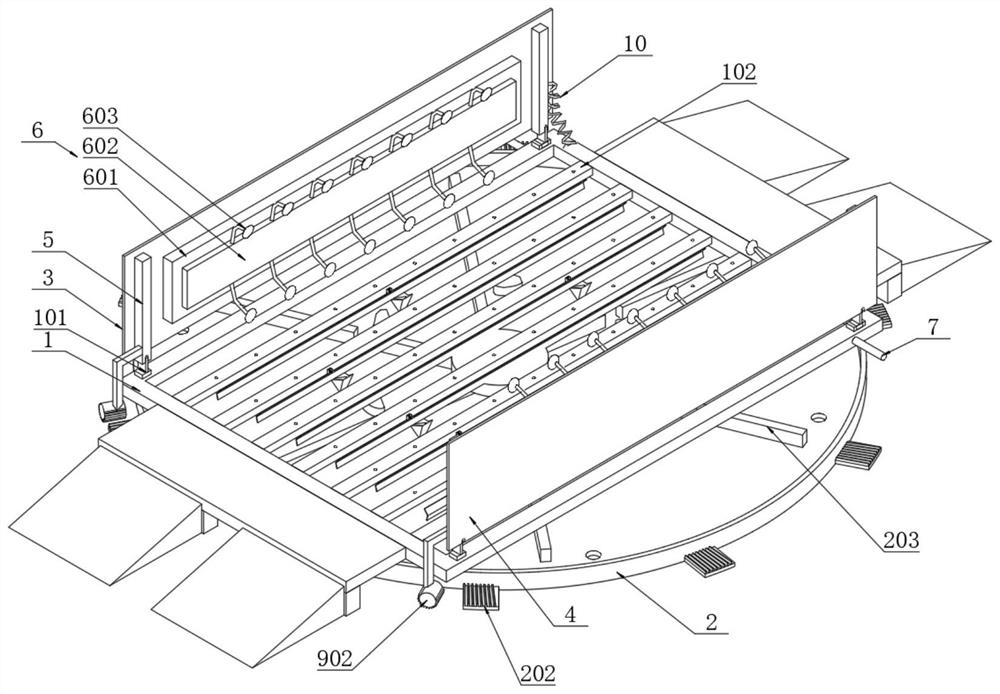
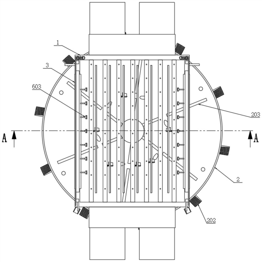
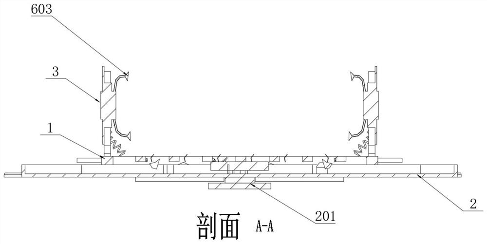
The invention relates to the technical field of building construction, in particular to a vehicle body cleaning frame for building construction, and solves the problem that an existing cleaning frameis single in cleaning mode, the vehicle body cleaning frame structurally comprises a frame body, a left baffle, a right baffle and a spraying seat mechanism, and rotating seats are installed on the two sides of the top surface of the frame body; stay bars are arranged on the two sides of the top of the frame via the rotating seats, the left baffle is rotationally installed on the left supporting rod, the number of the spraying base mechanisms is two, and the two spraying base mechanisms are fixed to the left baffle and the right baffle and can rotate and swing inwards and outwards along with the left baffle and the right baffle. Therefore, the purpose of swing type cleaning can be achieved when the two spray seats spray water to clean the side portion of the vehicle, due to the fact that the swing type cleaning device acts in linkage with the rotating cabin, electric energy is saved when the two spray seats act, and the swing type cleaning device has the structural advantages of beingsimple in structure and convenient to maintain. A motor driving mode is adopted, three functions and structures of sewage collection, upper flushing action and side flushing action are unified, and the structural design is ingenious and reasonable.

Description

technical field [0001] The invention relates to the technical field of building construction, in particular to a vehicle body cleaning rack for building construction. Background technique [0002] During the building construction process, the construction equipment used will leave a lot of soil or silt on the surface during the application process. Therefore, after construction, the car body needs to be cleaned. The more commonly used cleaning mechanism is the construction car body cleaning rack. There are cleaning pipes or nozzles installed, and the nozzles are mostly located at the bottom of the frame body, and the sludge at the bottom of the vehicle is cleaned by flushing upwards, but only for the bottom of the vehicle, the flushing method is relatively simple, and the cleaning effect is poor. The cleaning frame of the side cleaning mechanism requires separate drive mechanisms on both sides of the cleaning frame to drive the cleaning action of the side cleaning mechanism,...

Claims


Application Information

Patent Timeline
Patent Type & Authority Applications(China)
IPC IPC(8): B60S3/04
CPCB60S3/04
Inventor 王大将倪赐圭
Owner 华港安城投资有限公司
Learn More