Composite flexible pipe laying device
A laying device and composite flexible technology, which is applied in the field of composite flexible pipe laying devices, can solve the problems of lack of operating equipment and achieve the effect of saving labor and working hours
- Summary
- Abstract
- Description
- Claims
- Application Information
AI Technical Summary
Problems solved by technology
Method used
Image
Examples
Embodiment 1
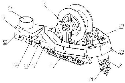
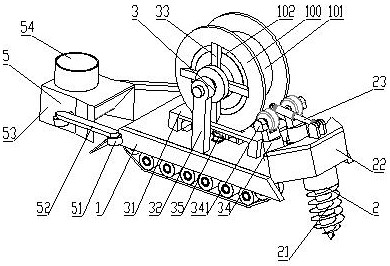
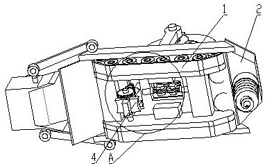
[0041] see Figure 1 to Figure 3 , the present invention provides a composite flexible pipe laying device, comprising a tunneling mechanism 2 at the front end of the car body 1, a support mechanism 3 arranged above the middle of the car body 1 to support the composite flexible pipe roller body, and a support mechanism 3 arranged at the rear end of the car body 1 A soil compacting mechanism 5, and a pipe pulling mechanism 4 is also arranged under the middle part of the vehicle body 1;
[0042] The driving mechanism 2 comprises a driving rod 21, the body of the driving rod 21 is provided with spiral blades, the bottom of the driving rod 21 is a tip, and the top is linked with the driving mechanism motor, and the driving mechanism motor rotates the driving rod 21, and the top of the driving rod 21 is arranged There is a driving mechanism housing 22, one side of the driving mechanism housing 22 is hinged with the car body 1, and the top of the driving mechanism housing 22 is hinge...
Embodiment 2
[0058] see Figure 4 , on the basis of Embodiment 1, the main support plate 31 and the car body 1 are vertically provided with openings for passing through the composite flexible pipe, the pipe pulling mechanism 4 includes a pipe drawing assembly, and the pipe drawing assembly is provided with two groups, They are respectively arranged in the openings of the main support plate 31 and the vehicle body 1. Each pull tube assembly includes two pull tube discs 411 oppositely arranged, and each pull tube disc 411 is rotatably connected to a horizontal bar. 412, the end of the cross bar 412 away from the pull tube disc 411 is fixed on the side wall of the opening;
[0059] On the disc of the pipe-drawing disc 411, a groove is provided along its circumferential surface, the groove is an arc-shaped groove, and the diameter of the groove is less than or equal to the outer diameter of the composite flexible pipe;
[0060] The cross bar 412 is an electric telescopic rod, and it can speci...
Embodiment 3
[0063] On the basis of Embodiment 2, the pulling mechanism 4 also includes a pressing tube assembly, which is arranged on the rear side of the opening of the vehicle body 1, and the pressing tube assembly includes a vertical rod 421 vertically arranged on the lower side of the vehicle body 1 , the vertical rod 421 is an electric telescopic rod, as above, its drive mode can be an electric push rod driven by a motor, a pneumatic or hydraulic push rod; device 422;
[0064] The tube crimping device 422 includes two plates combined in a cross shape, and an arc-shaped groove is provided at the outer end of each plate body, and a horizontal rotating shaft is fixedly arranged at the cross-shaped combination of the tube crimping device 422, through which the tubes are crimped. Device 422 is rotatably connected with the gantry.
[0065] The rotating shaft of the tube crimping device 422 extends to the outside of the gantry, and one end of the rotating shaft outside the gantry is fixedl...
PUM
 Abstract
Description
Claims
Application Information
 - R&D Engineer
- R&D Manager
- IP Professional
- Industry Leading Data Capabilities
- Powerful AI technology
- Patent DNA Extraction
Browse by: Latest US Patents, China's latest patents, Technical Efficacy Thesaurus, Application Domain, Technology Topic, Popular Technical Reports.
© 2024 PatSnap. All rights reserved.Legal|Privacy policy|Modern Slavery Act Transparency Statement|Sitemap|About US| Contact US: help@patsnap.com


