
Aluminum bottle cap channeling machine

A technology of rolling groove machine and bottle cap, which is applied in capping, packaging, closing and other directions, which can solve the problems of cumbersome operation and high energy consumption, and achieve the effect of increasing work efficiency and reducing time consumption

Active Publication Date: 2021-03-23
浙江冠利新材料股份有限公司
View PDF6 Cites 1 Cited by
  • Summary
  • Abstract
  • Description
  • Claims
  • Application Information

AI Technical Summary

Problems solved by technology

[0004] The purpose of the present invention is to solve the problems in the prior art that the operation is more cumbersome and energy consumption requires another power source to control the detachment of the roller from the bottle cap, and the problem of high energy consumption, and proposes an aluminum bottle cap rolling machine

Method used


Image

  • Aluminum bottle cap channeling machine
  • Aluminum bottle cap channeling machine
  • Aluminum bottle cap channeling machine

Examples


Embodiment

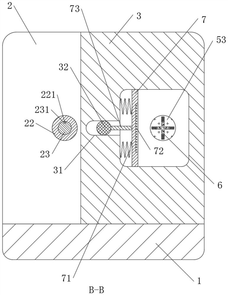
[0026] refer to Figure 1-5 , an aluminum bottle cap rolling machine, including a base 1, the upper end of the base 1 is welded with a first column 2 and a second column 3, the first column 2 and the second column 3 offset each other, and the side wall of the first column 2 runs through Rotationally connected with a first rotating rod 21, the side wall of the first rotating rod 21 is provided with a horizontal groove 22, and the inner wall of the horizontal groove 22 is slidably connected with a sliding rod 23, one end of the sliding rod 23 is located inside the horizontal groove 22, and the other end of the sliding rod 23 is located in the horizontal groove 22. The outside of the horizontal groove 22 is welded with a connecting block 24 on the side wall of the sliding rod 23 outside the horizontal groove 22, and the side wall of the second column 3 is provided with a sliding groove 31, and the inner wall of the sliding groove 31 is slidably connected with a fixed rod 32, and t...


PUM


Abstract

The invention discloses a aluminum bottle cap channeling machine. The aluminum bottle cap channeling machine comprises a base, a first stand column and a second stand column are welded to the upper end of the base, the first stand column abuts against the second stand column, a first rotating rod is rotatably connected to the side wall of the first stand column in a penetrating mode, a horizontalgroove is formed in the side wall of the first rotating rod, a sliding rod is slidably connected to the inner wall of the horizontal groove, one end of the sliding rod is located inside the horizontalgroove, the other end of the sliding rod is located outside the horizontal groove, a connecting block is welded to the side wall, located outside the horizontal groove, of the sliding rod, and a sliding groove is formed in the side wall of the second stand column. According to the aluminum bottle cap channeling device, through arrangement of the sliding rod, a clamping block, a first rotating rodand a key groove, horizontal movement of the connecting block and a bottle cap can be achieved under slow driving of an electric push rod while the connecting block and the bottle cap are electrically driven by a driving motor to rotate, so that bottle cap external rolling work is easier to conduct, manual control does not need, and therefore, automatic processing of the bottle cap rolling groovecan be achieved.

Description

technical field [0001] The invention relates to the technical field of bottle cap grooving equipment, in particular to an aluminum bottle cap grooving machine. Background technique [0002] The bottle cap is used to seal the bottle. According to different functions, there are bottle caps with different shapes and different operation methods. The rolling groove is a method of smoothing or strengthening the groove on the workpiece with rolling tools. The bottle cap rolling The groove is to facilitate the cooperation with the bottle and realize the rotation installation, and the bottle cap rolling groove machine is the main machine for the bottle cap rolling groove processing; [0003] In the existing life, it is necessary to manually control the bottle cap and process it on the bottle cap grooving machine, and the existing bottle cap grooving machine cannot realize the detachment of the bottle cap from the roller, so it is impossible to directly take out the processed bottle c...

Claims


Application Information

Patent Timeline
IPC IPC(8): B21D17/04B21D51/48
CPCB21D17/04B21D51/48Y02P70/10
Inventor 陈国伟姚卫峰
Owner 浙江冠利新材料股份有限公司
Learn More