Reactive voltage control method and system

A voltage control method and bus voltage technology, applied in reactive power compensation, AC network voltage adjustment, etc.

Active Publication Date: 2021-03-19
CHINA ELECTRIC POWER RES INST
View PDF6 Cites 0 Cited by
  • Summary
  • Abstract
  • Description
  • Claims
  • Application Information

AI Technical Summary

Problems solved by technology

[0007] The technical solution of the present invention provides a reactive voltage control method and system to solve the problem of how to control reactive voltage

Method used


Image

  • Reactive voltage control method and system
  • Reactive voltage control method and system
  • Reactive voltage control method and system

Examples


Embodiment Construction

[0094] Exemplary embodiments of the present invention will now be described with reference to the drawings; however, the present invention may be embodied in many different forms and are not limited to the embodiments described herein, which are provided for the purpose of exhaustively and completely disclosing the present invention. invention and fully convey the scope of the invention to those skilled in the art. The terms used in the exemplary embodiments shown in the drawings do not limit the present invention. In the figures, the same units / elements are given the same reference numerals.

[0095]Unless otherwise specified, the terms (including scientific and technical terms) used herein have the commonly understood meanings to those skilled in the art. In addition, it can be understood that terms defined by commonly used dictionaries should be understood to have consistent meanings in the context of their related fields, and should not be understood as idealized or overl...


PUM


Abstract

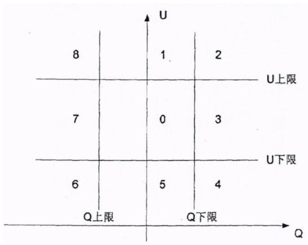
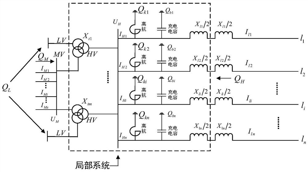
The invention discloses a reactive voltage control method and system. The method comprises the following steps: acquiring a high-voltage side bus voltage UH; when the UH is greater than the preset upper limit value of the high-voltage side bus voltage, reducing the UH to be lower than the preset value and higher than the lower limit value of the high-voltage side bus voltage; raising the UH aboveand below when the UH is less than a preset value; when the UH is between the QH and the QM, calculating the sum QH of reactive power injection to the local system at the midpoints of all lines of thehigh-voltage side, calculating the sum QM of reactive power injection to the local system at the medium-voltage side, calculating the sum QHM of the QH and the QM, and judging whether the absolute value of the QHM is greater than a preset local system reactive power demand balance threshold Qequi; when the QHM is greater than the Qequi, putting a group of capacitive reactive power compensation equipment into use or removing a group of inductive reactive power compensation equipment; and when the negative number of the QHM is greater than Qequi, putting a group of inductive reactive power supplementing equipment into use.

Description

technical field [0001] The present invention relates to the technical field of reactive voltage analysis and control of power systems, and more specifically, to a reactive voltage control method and system. Background technique [0002] The problem of reactive power and voltage control has become increasingly prominent in high-proportion new energy power systems. Large-scale wind power, photovoltaic and other new energy bases are generally located in remote places, and often need to be connected and transmitted to the main grid through long-distance AC transmission lines. However, new energy power generation is intermittent and volatile, so the active power flow on the AC line fluctuates greatly and frequently, causing reactive power loss and voltage fluctuations are also very severe and frequent, making it difficult to control the reactive power and voltage of the transmission system, high / low The voltage limit problem is serious, which leads to a high risk of disconnectio...

Claims


Application Information

Patent Timeline
IPC IPC(8): H02J3/16
CPCH02J3/16Y02E40/30
Inventor 秦晓辉张立波代倩杨京齐
Owner CHINA ELECTRIC POWER RES INST
Why Eureka
Try Eureka