Large-aperture telescope supporting assembly

A technology for supporting components and telescopes, applied in the field of space remote sensing, can solve the problems of low precision, damage to the mirror body, and long time consumption, and achieve the effects of ensuring accuracy, avoiding crushing, and convenient positioning

Pending Publication Date: 2021-03-19
CHANGCHUN INST OF OPTICS FINE MECHANICS & PHYSICS CHINESE ACAD OF SCI
View PDF3 Cites 1 Cited by
  • Summary
  • Abstract
  • Description
  • Claims
  • Application Information

AI Technical Summary

Problems solved by technology

[0003] The difficulty in the installation of large-diameter telescope support components is to accurately bond the Yin Gang pad to the support hole of the primary mirror and the surrounding mirror body. The traditional installation of large-diameter telescope support components relies on manual adjustment of the position of the Yin Gang pad. Long time, low accuracy, serious and even damage to the mirror body

Method used


Image

  • Large-aperture telescope supporting assembly
  • Large-aperture telescope supporting assembly
  • Large-aperture telescope supporting assembly

Examples


Embodiment 1

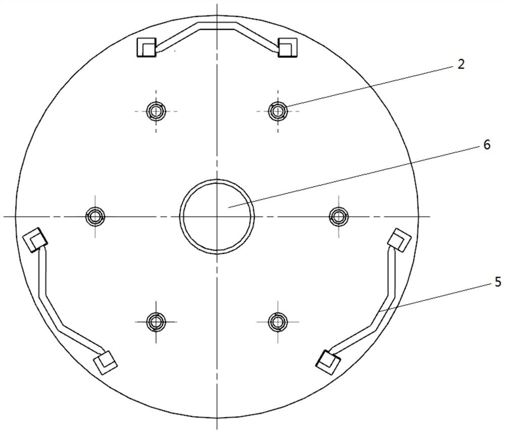
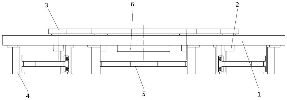
[0038] An embodiment of the present application provides a support assembly for a primary mirror of a large-aperture telescope, including a back support assembly and a peripheral support assembly. The primary mirror is arranged on the top of the back support assembly, and the peripheral support assembly is arranged on the back support assembly. At the bottom, the main mirror central positioning sleeve (6) is arranged on the back support assembly, and the main mirror central positioning sleeve (6) is coaxial with the central axis of the back support assembly.

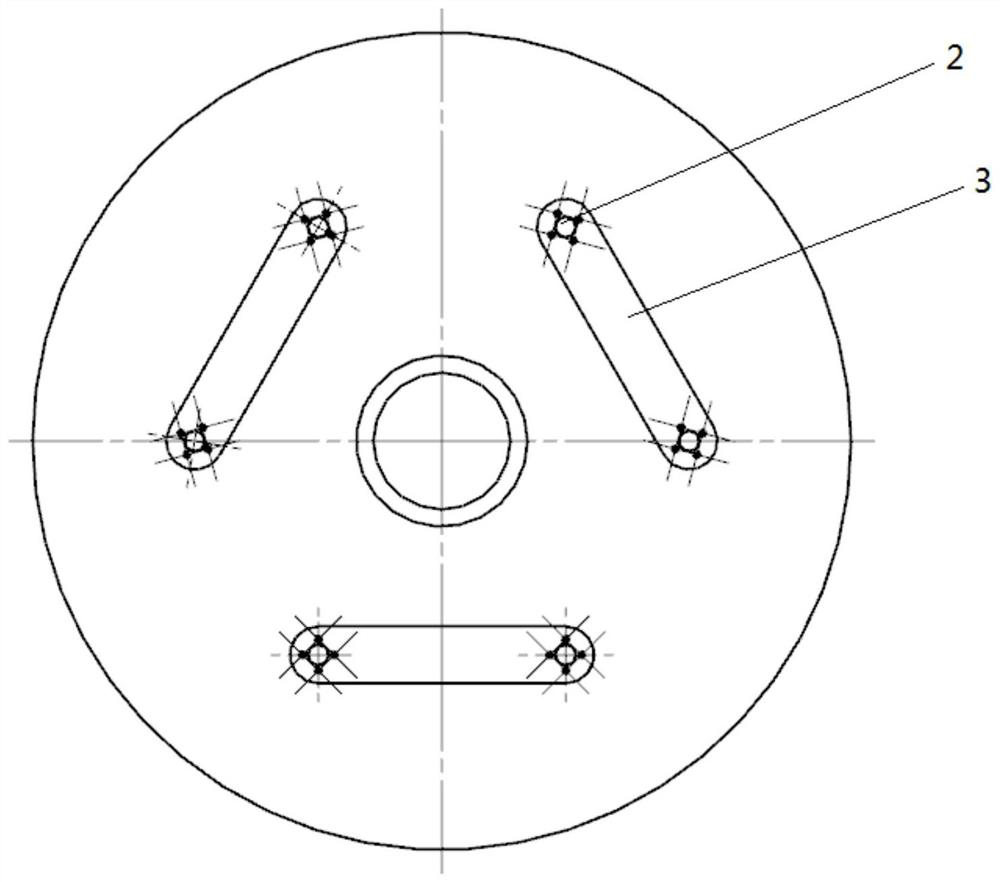
[0039] The back support assembly comprises a back cover plate (1), a back positioning bushing (2), and a back positioning bushing connecting a cross bar (3). 6 holes are evenly arranged on the back cover plate (1), and the back positioning bushings (2) matched therewith are respectively arranged in the 6 holes; the back positioning bushings (2) can avoid the main mirror The mirror body is crushed by the circular back cov...

Embodiment 2

[0045] The embodiment of the present application provides a method for positioning the main mirror support assembly of a large-aperture telescope, including the following specific steps:

[0046] 1. The positioning of the back support assembly, so that the back cover (1) and the main mirror are installed together:

[0047] 1) Place the primary mirror of the support assembly to be installed facing downward;

[0048] 2), place the back positioning bushing (2) in the positioning hole of the back cover plate (1) through the screw hole on the back positioning bushing (2);

[0049] 3) Place the back cover (1) on the back of the main mirror through the back positioning bushing (2), and then determine the relative position of the main mirror and the back cover (1) through the center positioning bushing (6) of the main mirror;

[0050] 4), connect the back positioning bushing (2) by connecting the cross bar (3) with the back positioning bushing provided with threaded holes, so as to r...


PUM


Abstract

A supporting assembly of a large-aperture telescope primary mirror comprises a back supporting assembly and a peripheral supporting assembly, the primary mirror is arranged at the top of the back supporting assembly through a primary mirror center positioning shaft sleeve, the peripheral supporting assembly is arranged at the bottom of the back supporting assembly, and the back supporting assemblycomprises a back cover plate, back positioning shaft sleeves and a back positioning shaft sleeve connecting cross rods. An even number of positioning holes are evenly formed in the back cover plate,the back positioning shaft sleeves matching the positioning holes are arranged in the positioning holes respectively, and each back positioning shaft sleeve is connected with an adjacent back positioning shaft sleeve through a back positioning shaft sleeve connecting cross rod. The peripheral supporting assembly comprises an even number of peripheral positioning grooves, peripheral positioning clamping arms and peripheral supporting cushion blocks, grooves which match the peripheral positioning grooves and used for bonding wedge-shaped faces are formed in the bottom of the back cover plate, each peripheral positioning groove is connected with an adjacent peripheral positioning groove through a peripheral positioning clamping arm, and the peripheral supporting cushion blocks are arranged inthe peripheral positioning grooves. According to the supporting assembly, accurate positioning can be achieved.

Description

technical field [0001] The present application relates to the technical field of space remote sensing, in particular to a large-aperture telescope support assembly. Background technique [0002] The field of space remote sensing technology is one of several key technical fields in which the developed countries compete fiercely. With the continuous improvement of the resolution and detection sensitivity of space remote sensors, the aperture of the reflector is getting larger and larger, and the requirements for the support performance of the reflector are also getting higher and higher. Reflector components are the key parts of space optical remote sensors, which are usually required to have good thermal and mechanical properties, and from the perspective of launch costs, the quality of components is limited by strict requirements. Therefore, the performance of the mirror assembly is directly related to the performance of the space remote sensor. [0003] The difficulty in ...

Claims


Application Information

Patent Timeline
Patent Type & Authority Applications(China)
IPC IPC(8): G02B23/16
CPCG02B23/16
Inventor 李巍罗致帮徐佳坤王克军王晓东董吉洪
Owner CHANGCHUN INST OF OPTICS FINE MECHANICS & PHYSICS CHINESE ACAD OF SCI
Why Eureka
Try Eureka