Measuring controllable differential drilling-reaming two-purpose drill rig

A differential type, drilling rig technology, used in construction, sheet pile wall, infrastructure engineering and other directions, can solve the problems of inability to monitor and control the reaming process, the efficiency is too high, the drill bit mechanism is too large, etc., to achieve detection and procedures. Simple and easy control, simple structure, light and efficient, simple and reasonable force

Inactive Publication Date: 2003-10-22
天津开发区三友新科技开发有限公司
View PDF7 Cites 0 Cited by
  • Summary
  • Abstract
  • Description
  • Claims
  • Application Information

AI Technical Summary

Problems solved by technology

The technical solution to the hole reaming problem proposed in the above-mentioned patents, due to the restriction of the selected reaming method and the reaming mechanism, has problems such as: the process of drilling and reaming two-time molding is complicated and the efficiency is insufficient, and Due to the unreasonable force on the reaming knife, the drill mechanism is too large, bulky and inefficient, and the problem that the reaming process cannot be monitored and controlled
[0003] After analyzing the above-mentioned various patented technical solutions, it can be found that the improvement of the drilling rig function and the improvement of the drill bit as elements in the overall solution are not considered and improved in the solutions, but the existing drilling rig is simply used. , and on the basis of the traditional drilling concept, try to solve the problem of reaming only by improving the drill bit, so it is inevitable to regret

Method used


Image

  • Measuring controllable differential drilling-reaming two-purpose drill rig
  • Measuring controllable differential drilling-reaming two-purpose drill rig
  • Measuring controllable differential drilling-reaming two-purpose drill rig

Examples


Embodiment Construction

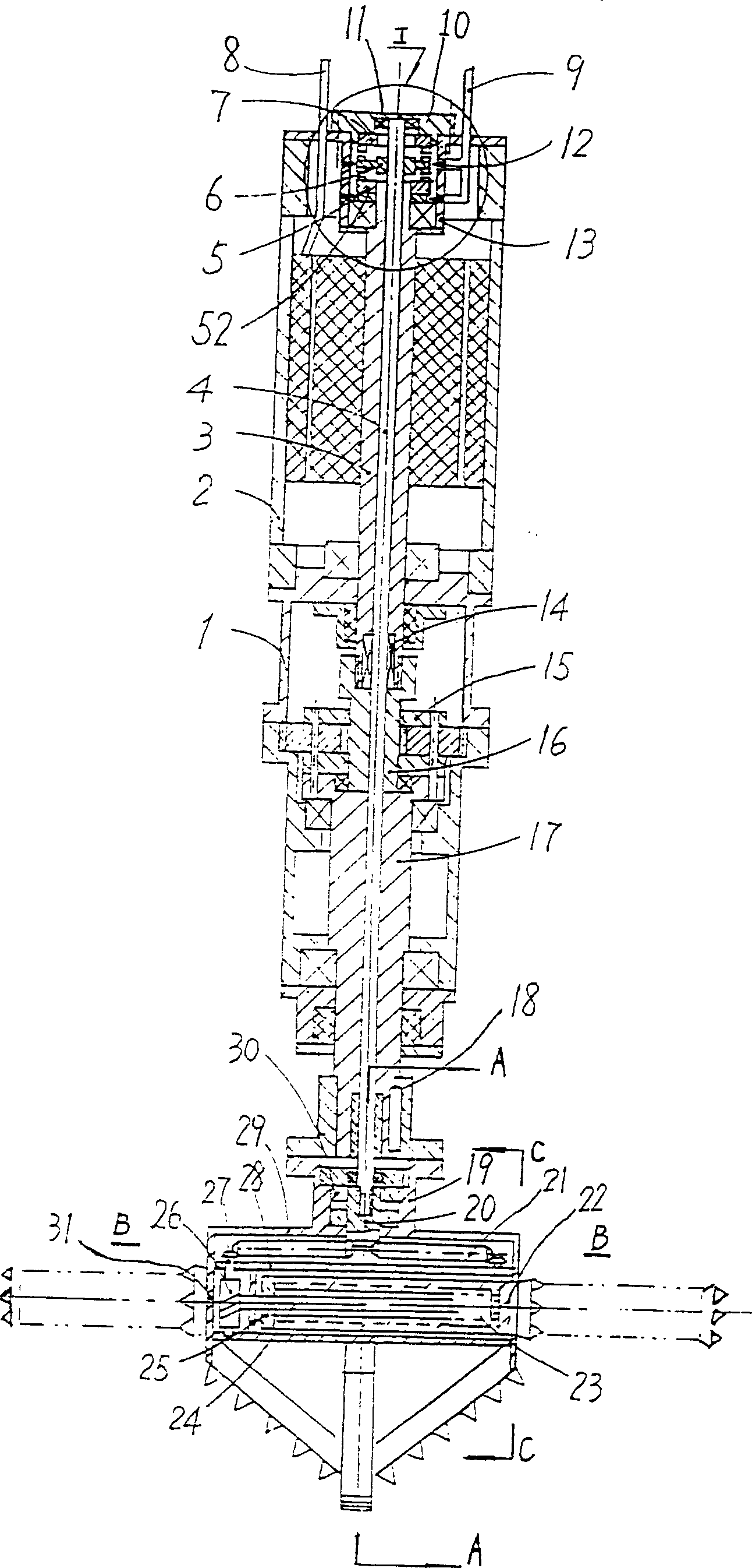
[0036] The measurable and controllable differential drilling and reaming dual-purpose drilling rig 1 shown in Fig. 1 is composed of a submersible motor 2, a planetary reducer 15, a drilling machine shaft 17 and a flange 18 on the shaft to form the power transmission route of the drilling machine 1 drilling. At this moment, the power cable 8 feeds the current into the stator coil of the submersible motor 2, and the motor rotor and the motor shaft 3 are rotated under the action of its magnetic field force, and the shaft 3 is connected to the sun gear shaft 16 and the Its star wheel and planetary gear frame rotate, and drive the drilling machine shaft 17 that is fixedly connected with the planetary wheel frame to rotate, connect the flange 18 on the drilling machine 17 with the flange of the drill bit 19, transmit power to the drill bit 19 and drive the drill bit 19 to rotate drilling.

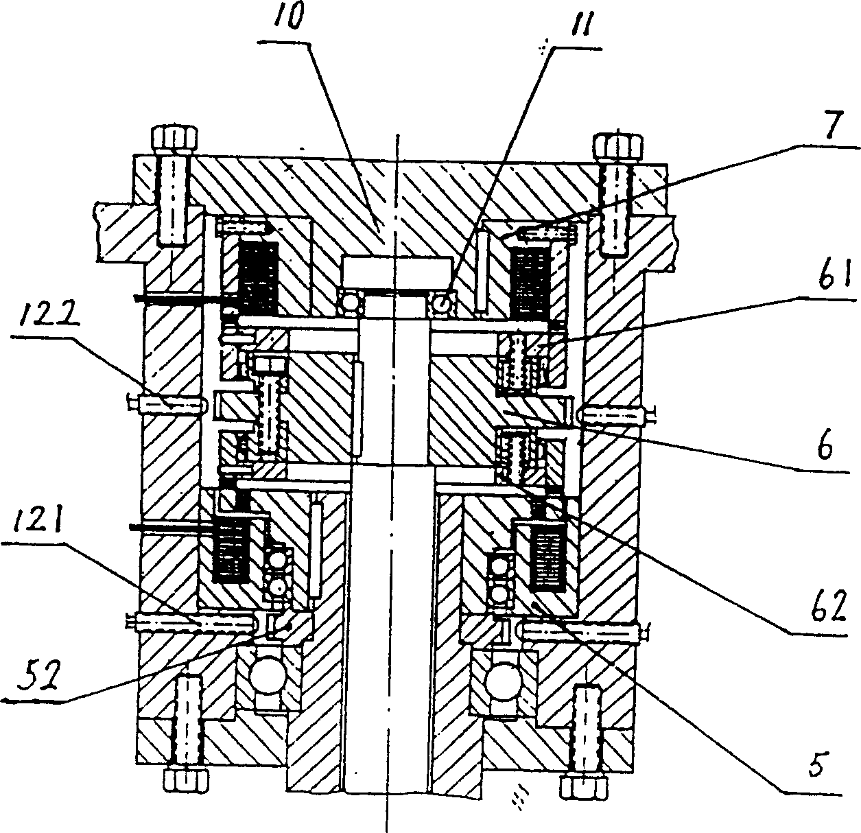
[0037]In order to make the drilling machine 1 form a differential output, the magnetic yoke 5...


PUM


Abstract

The differential drilling and expanding dual-purpose drilling machine is characterized by that a control shaft is set in the interior of central through hole opened in the submersible motor shaft centre, central gear shaft centre of planetary reducer and drill shaft centre, and the stop and rotation of said control shaft or isospeed rotation of it with submersible motor can be controlled by its upper end placed electromagnetic brake and electromagnetic clutch. The upper pontion of drill bit is equipped with a drill cross-beam, the lower portion of cross-beam is equipped with two expanding toolbars which are symmertrically arranged, and the drill central shaft and drill cross-beam are driven by differential driving mechanism, and can be used to drive expanding toolbars and make them implement horizontal expanding movement. Two groups of revolution detectors for detecting motor shaft revolution and control shaft revolution are set by motor shaft and by control shaft.

Description

technical field [0001] The invention belongs to a drilling rig used for pile foundation construction in construction engineering, and is mainly used for drilling and reaming construction of multi-stage reaming piles. Background technique [0002] At present, around the hole forming problem of multi-stage reaming piles, a number of patented technical solutions have been disclosed. For example: the patents (ZL89107846.0) and (ZL99205417.6) which are characterized by the use of two-link extruding plates to rotate and extrude the hole wall step by step in drilling holes; Hole knife, by extrusion to make the cantilever of the two-link reaming knife protrude out, the patents of rotary cutting and reaming are (ZL95213581.2), (ZL97213085.3) and (ZL99228453.8); The patents that the rotating extrusion reaming cutter stretches out the rotating cutting reaming by the cantilever are (ZL97213123.8) and (ZL97213124.6). The technical solution to the hole reaming problem proposed in the ab...

Claims


Application Information

Patent Timeline
Patent Type & Authority Patents(China)
IPC IPC(8): E02D5/44E02D5/48E02D7/22
Inventor 杨政魏兆华卢英琨
Owner 天津开发区三友新科技开发有限公司
Why Eureka
Try Eureka