Compton camera with segmented detection modules

A Compton camera and detector technology, used in measurement devices, radiation measurement, radiation intensity measurement, etc., can solve problems such as lack of design and constraint requirements, lack of integration, etc.

Pending Publication Date: 2021-03-16
SIEMENS MEDICAL SOLUTIONS USA INC
View PDF0 Cites 0 Cited by
  • Summary
  • Abstract
  • Description
  • Claims
  • Application Information

AI Technical Summary

Problems solved by technology

Current solutions lack the ability to integrate into imaging platforms in the clinic, or lack the design and constraints required to address commercial needs (i.e., flexibility and scalability)

Method used


Image

  • Compton camera with segmented detection modules
  • Compton camera with segmented detection modules
  • Compton camera with segmented detection modules

Examples


Embodiment Construction

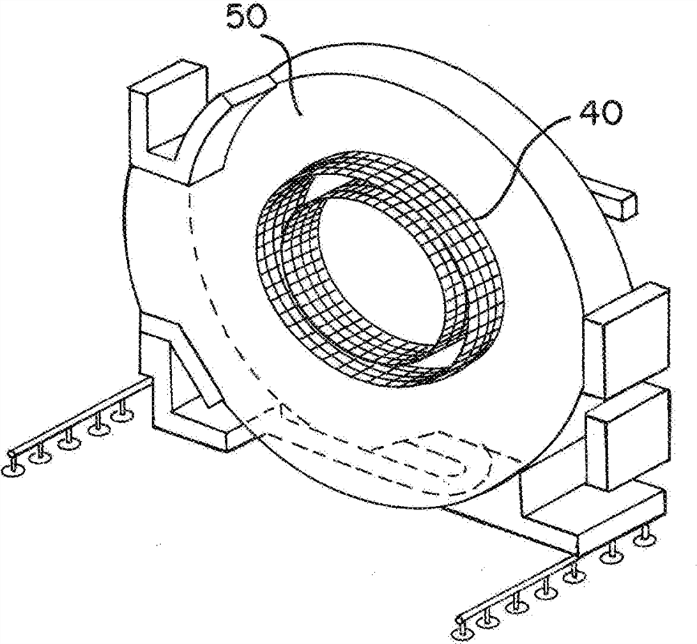
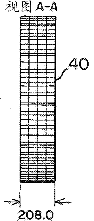
[0018] The medical imaging system includes a multi-modality compatible Compton camera with a segmented detection module. Compton cameras, such as Compton camera rings, are segmented into modules that house detection units. Each module is independent, and when assembled into a ring or partial ring, the modules can communicate with each other. The modules are self-contained but can be assembled into a multi-module unit that produces images based on Compton scattering. Cylindrical symmetric modules or spherical shell segment modules can be used.

[0019] The scatter-catcher pair, modular arrangement allows for efficient manufacture, is field serviceable, and is cost and energy efficient. These modules allow design freedom to vary the radius of each radial detection unit, the angular span of a module and / or the axial span. The scatter-capture pair modules are multimodal compatible and / or form a modular annular Compton camera for clinical radiography. The design allows flexibil...


PUM


Abstract

A Compton camera for medical imaging is divided into segments (11) with each segment (11) including part of the scatter detector (12), part of the catcher detector (13), and part of the electronics (14). The different segments (11) may be positioned together to form the Compton camera arcing around part of the patient space. By using segments (11), any number of segments (11) may be used to fit with a multi-modality imaging system.

Description

Background technique [0001] This embodiment relates to a Compton medical imaging system. The Compton imaging system is constructed as a test bed, eg, to assemble a scattering ring and, subsequently, a catcher ring mounted to a large frame. Electronics are connected to detect Compton-based events from the phantom's radiation. Compton imaging systems fail to meet the design and constraints required for practical use in any commercial clinical setting. Current approaches lack the ability to integrate into imaging platforms in the clinic, or lack the design and constraint requirements (ie, flexibility and scalability) to address commercial needs. SUMMARY OF THE INVENTION [0002] By way of introduction, the preferred embodiments described below include methods, systems and Compton cameras for medical imaging. The Compton camera is divided into sections, where each section includes a portion of a scatter detector, a portion of a capture detector, and a portion of the electroni...

Claims


Application Information

Patent Timeline
IPC IPC(8): G01T1/00A61B6/00G01T1/164G01T1/29G01T1/24
CPCG01T1/29G01T1/2985A61B6/4258A61B6/4266A61B6/4275A61B6/4411A61B6/4417A61B6/4429A61B6/483A61B6/032A61B6/037A61B6/06A61B6/4488
Inventor A·H·维贾M·罗德里格斯J·F·卡鲁巴
Owner SIEMENS MEDICAL SOLUTIONS USA INC
Why Eureka
Try Eureka