Optical lens and imaging equipment
A technology of optical lens and imaging surface, which is applied in the field of imaging lens, can solve the problems of large size and sacrificing viewing angle, and achieve the effect of achieving high pixel balance, miniaturization, and improving camera experience
- Summary
- Abstract
- Description
- Claims
- Application Information
AI Technical Summary
Problems solved by technology
Method used
Image
Examples
Embodiment approach
[0028] As an implementation, the optical lens satisfies the following conditional formula:
[0029] 1.6
[0030] Among them, TTL represents the total optical length of the optical lens, and IH represents the actual half-image height of the optical lens.
[0031] When conditional formula (1) is satisfied, the total optical length of the optical lens can be reasonably controlled, which is conducive to achieving a balance between lens miniaturization and wide viewing angle.
[0032] As an implementation, the optical lens can also satisfy the following conditional formula:
[0033] 0.5
[0034] Wherein, DM1 represents the effective radius of the first lens, and HFOV represents the maximum half field of view of the optical lens.
[0035] When the conditional formula (2) is satisfied, the depth of field of the optical lens can be reasonably controlled, and the head size of the optical lens can be made smaller, which is conducive to reducin...
no. 1 example
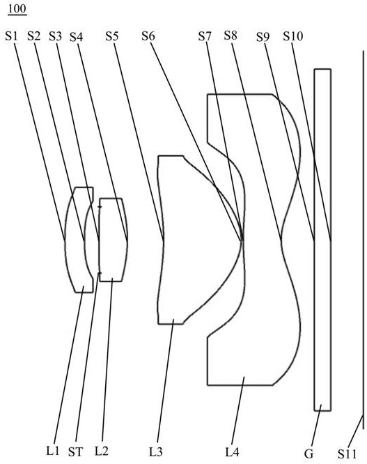
[0080] see figure 1 , an optical lens 100 provided by the first embodiment of the present invention includes, from the object side to the imaging surface in sequence: a first lens L1, a stop ST, a second lens L2, a third lens L3, a fourth lens L4 and a filter slice G.
[0081] Wherein, the first lens L1 has negative refractive power, the object side S1 of the first lens is convex, and the image side S2 of the first lens is concave.
[0082] The second lens L2 has positive refractive power, the object side S3 of the second lens is convex, and the image side S4 of the second lens is convex.
[0083] The third lens L3 has positive refractive power, the object side S5 of the third lens is concave at the near optical axis and has at least one inflection point, and the image side S6 of the third lens is convex.
[0084] The fourth lens L4 has negative refractive power, the object side S7 of the fourth lens is a convex surface at the near optical axis, the image side S8 of the four...
no. 2 example
[0096] The structure of the optical lens provided by the second embodiment of the present invention is substantially the same as that of the optical lens 100 provided by the first embodiment, except that the radius of curvature and material selection of each lens are different. In the second embodiment of the present invention, the vertical distance between the inflection point of the object side surface S5 of the third lens and the optical axis is 0.795 millimeters.
[0097] Please refer to Table 3, which shows the relevant parameters of each lens in the optical lens provided by the second embodiment of the present invention.
[0098] table 3
[0099]
[0100] Please refer to Table 4, which shows the surface coefficients of each aspheric surface of the optical lens provided by the second embodiment of the present invention.
[0101] Table 4
[0102]
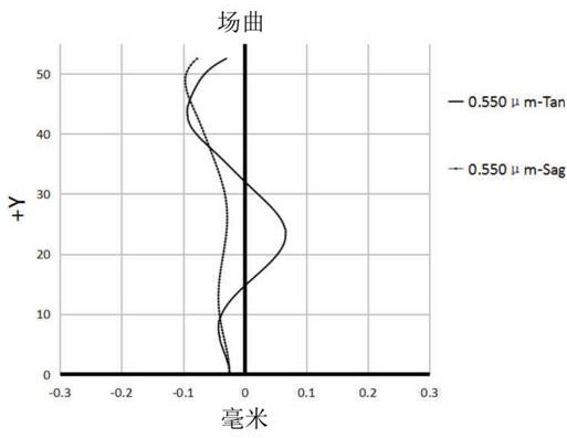
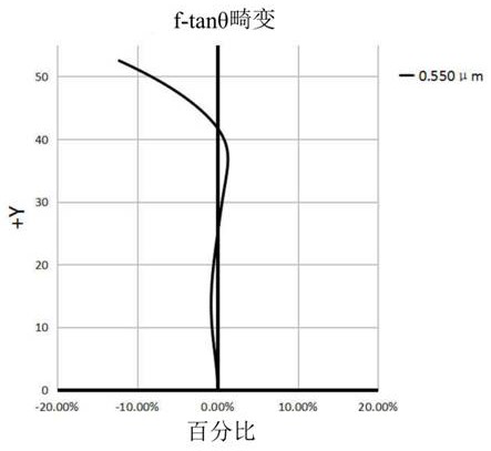
[0103] Please refer to Figure 5 , Image 6 and Figure 7 , respectively showing the astigmatism curve, the distort...
PUM
 Abstract
Description
Claims
Application Information
 - Generate Ideas
- Intellectual Property
- Life Sciences
- Materials
- Tech Scout
- Unparalleled Data Quality
- Higher Quality Content
- 60% Fewer Hallucinations
Browse by: Latest US Patents, China's latest patents, Technical Efficacy Thesaurus, Application Domain, Technology Topic, Popular Technical Reports.
© 2025 PatSnap. All rights reserved.Legal|Privacy policy|Modern Slavery Act Transparency Statement|Sitemap|About US| Contact US: help@patsnap.com


