Hydraulic operating mechanism and hydraulic control valve
A technology of hydraulic control valve and hydraulic operation, applied in contact drive mechanism, fluid pressure actuating device, mechanical equipment, etc., can solve the problems of high manufacturing precision, inconvenient maintenance, complicated assembly, etc., and achieve the goal of reducing manufacturing precision. requirements, ease of maintenance, and ease of assembly
- Summary
- Abstract
- Description
- Claims
- Application Information
AI Technical Summary
Problems solved by technology
Method used
Image

Examples
Embodiment 2
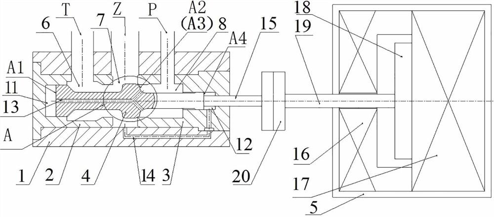
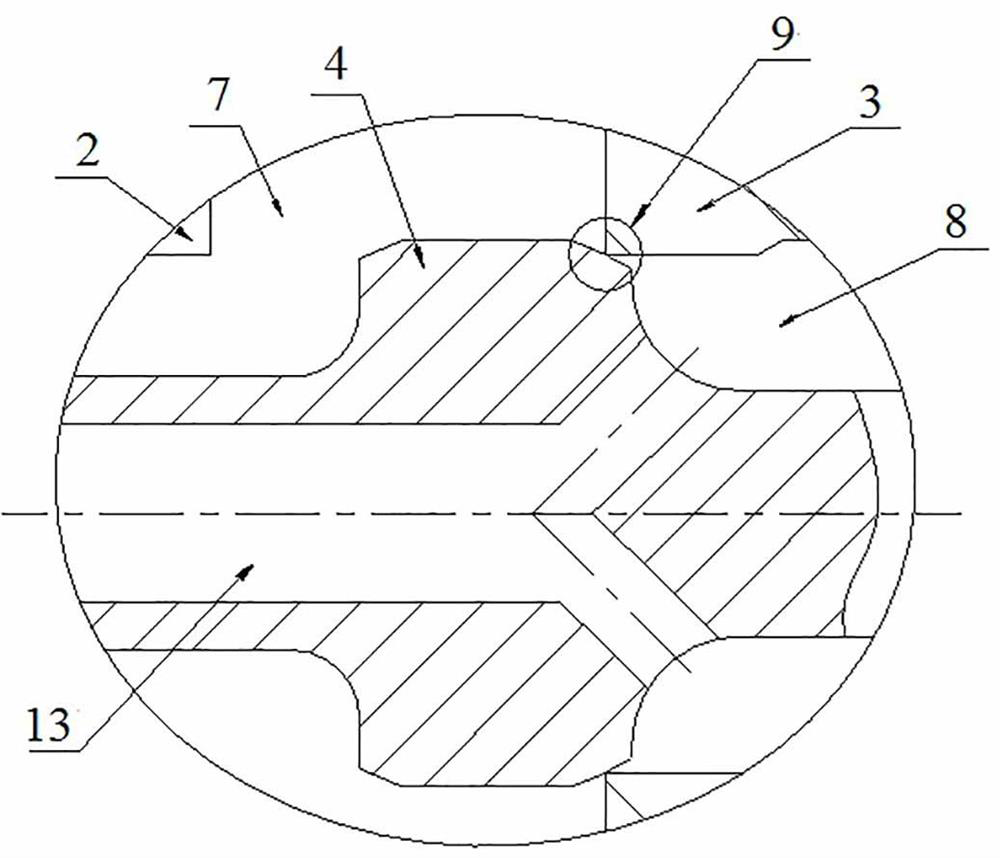
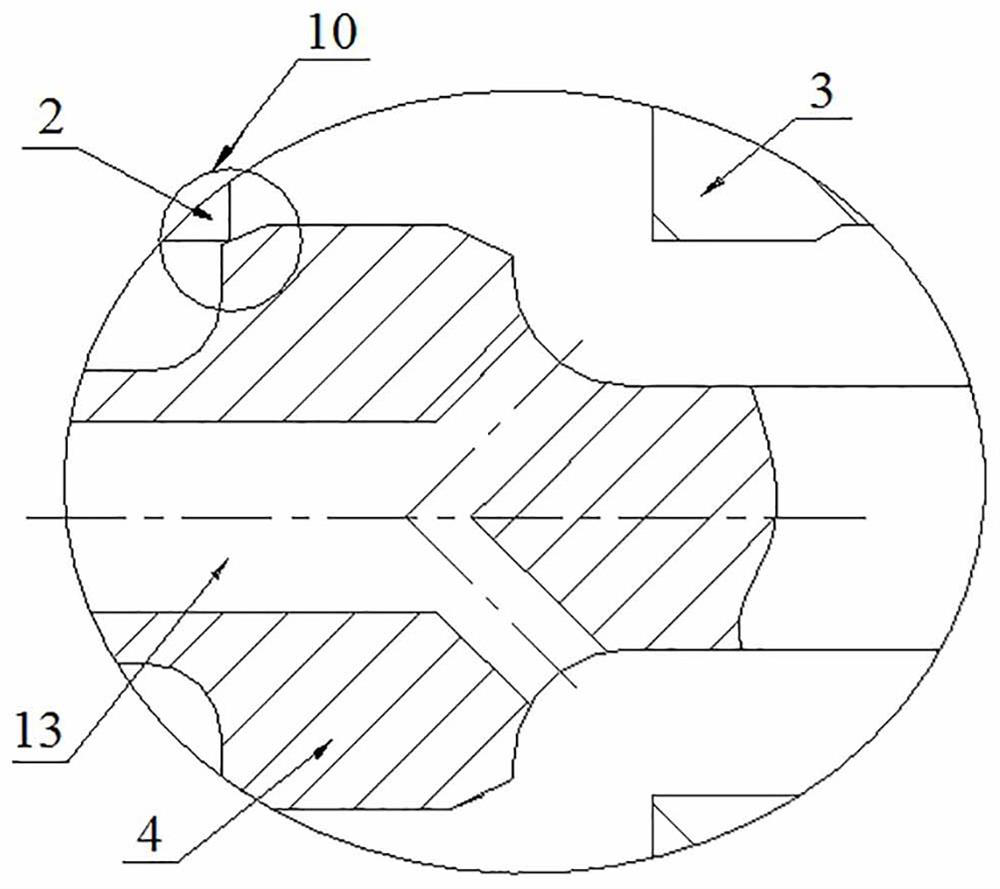
[0074] Such as Figure 4 As shown, the difference between this embodiment and Embodiment 1 is that in Embodiment 1, the driving rod 15 and the repulsion module are arranged on the right side of the spool 4, and the channel 13 of the left moving area is arranged in the spool 4, while the present embodiment In the embodiment, the driving rod 15 and the repulsion module are arranged on the left side of the valve core 4. In order to avoid the influence of the driving rod 15 on the channel 13 of the left moving area, the channel 13 of the left moving area is arranged in the valve body, and the effective end surface area A1 is reduced. , A4 increases, but still satisfies A1>A2, and A1
Embodiment 3
[0076] Such as Figure 5 and Figure 6 As shown, the difference between this embodiment and Embodiment 1 is that in Embodiment 1, the driving rod 15 and the repulsion module are arranged on the right side of the spool 4, and the left moving area channel 13 is arranged in the spool 4, while this embodiment In the embodiment, drive rods 15 and repulsion modules are provided on the left and right sides of the spool 4, and each drive rod 15 is arranged separately from the corresponding spool 4, and the corresponding end faces of the drive rod 15 and the spool 4 There is an interval between them; at this time, the repulsion modules all move in one direction, and the strokes of the repulsion modules are greater than the stroke of the spool 4, that is, the repulsion modules are stopped by the spool 4 and the valve body; because the drive rod 15 on the left is in the Under the action of the high-pressure oil in the left moving area 11, it can move to the left to ensure the leftward r...
Embodiment 4
[0078] Such as Figure 7 As shown, the difference between this embodiment and Embodiment 3 is that in this embodiment, a length adjustment structure is provided between the output end of the repulsion module and the drive rod 15, and the length adjustment structure includes an adjustable connecting rod 22, which can be adjusted The two ends of the connecting rod 22 are provided with reverse threads, which are respectively threaded on the drive rod 15 and the transmission rod 19; the adjustable connecting rod 22 is also provided with a locking nut 23, which is used for locking and positioning after the adjustment is in place. ;By adjusting the wrench position in the middle of the adjustable connecting rod 22, the distance between the drive rod 15 and the corresponding end of the valve core 4 can be adjusted to meet different opening and closing time requirements, and the stop element can be changed, and the valve core 4 can be relied on. The stop between the valve bodies can al...
PUM
 Abstract
Description
Claims
Application Information
 - Generate Ideas
- Intellectual Property
- Life Sciences
- Materials
- Tech Scout
- Unparalleled Data Quality
- Higher Quality Content
- 60% Fewer Hallucinations
Browse by: Latest US Patents, China's latest patents, Technical Efficacy Thesaurus, Application Domain, Technology Topic, Popular Technical Reports.
© 2025 PatSnap. All rights reserved.Legal|Privacy policy|Modern Slavery Act Transparency Statement|Sitemap|About US| Contact US: help@patsnap.com