Fireproof high-voltage alternating-current power distribution cabinet

A high-voltage AC and AC power distribution technology, applied in substation/distribution device housing, busbar/line layout, seismic equipment, etc., can solve the problems of electrician safety hazards, electrician trouble, inconvenient line connection, etc., to avoid potential safety hazards , the effect of easy maintenance

Inactive Publication Date: 2021-03-12
东莞市斯皓实业有限公司
View PDF0 Cites 0 Cited by
  • Summary
  • Abstract
  • Description
  • Claims
  • Application Information

AI Technical Summary

Problems solved by technology

[0004] The purpose of the present invention is to provide a fire-proof high-voltage AC power distribution cabinet, which solves the problem of inconvenient installation and disassembly of the line switch when the existing fire-proof high-voltage AC power distribution cabinet is in use, and the inconvenient installation and removal of the line switch when the line switch is damaged. The switch should be replaced; the existing fire-proof high-voltage AC power distribution cabinet does not have an explosion-proof structure, and cannot effectively protect the circuit from being damaged by force; the existing fire-proof high-voltage AC power distribution cabinet does not have a board layer for installing line switches when in use Moving up and down is not convenient when connecting the line to the line switch, which brings trouble to the electrician, and at the same time makes the electrician have technical problems of potential safety hazards when connecting the line

Method used


Image

  • Fireproof high-voltage alternating-current power distribution cabinet
  • Fireproof high-voltage alternating-current power distribution cabinet
  • Fireproof high-voltage alternating-current power distribution cabinet

Examples


Embodiment Construction

[0026] The technical solutions of the present invention will be clearly and completely described below in conjunction with the embodiments. Apparently, the described embodiments are only some of the embodiments of the present invention, not all of them. Based on the embodiments of the present invention, all other embodiments obtained by persons of ordinary skill in the art without creative efforts fall within the protection scope of the present invention.

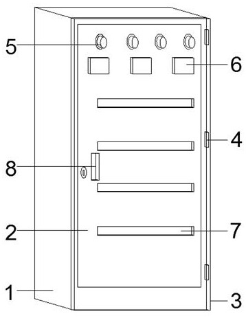
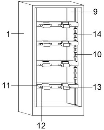
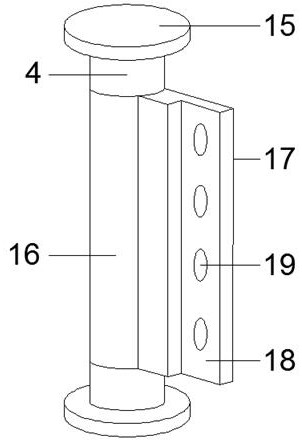
[0027] refer to Figure 1-5 As shown, a fireproof high-voltage AC power distribution cabinet includes an AC power distribution cabinet body 1, a cabinet body door panel 2 is installed on the front of the AC power distribution cabinet body 1, an explosion-proof glass plate 3 is installed on the front side of the cabinet body door panel 2, and the cabinet body Between the door panel 2 and the explosion-proof glass panel 3, a rotating buckle 4 connected to the cabinet door panel 2 and the explosion-proof glass panel 3 is insta...


PUM


Abstract

The invention discloses a fireproof high-voltage alternating-current power distribution cabinet which comprises an alternating-current power distribution cabinet body, a cabinet body door plate is installed on the front face of the alternating-current power distribution cabinet body, an explosion-proof glass plate is installed on the front face of the cabinet body door plate, and a rotating buckleconnected with the cabinet body door plate and the explosion-proof glass plate is installed at the side between the cabinet body door plate and the explosion-proof glass plate. Four groups of warningbuttons are mounted on the top side of the front surface of the cabinet body door plate, three groups of square transparent plates are mounted at the top end of the front surface of the cabinet bodydoor plate, the square transparent plates are positioned below the warning buttons, four groups of transparent long plates are mounted in the middle of the front surface of the cabinet body door plate, and a pull groove is formed in the middle of one side of the front surface of the cabinet body door plate. The fireproof high-voltage alternating-current power distribution cabinet has higher capabilities of connecting a high-voltage line and regulating and controlling electric energy, has fireproof and explosion-proof capabilities, is convenient for an electrician to switch over the high-voltage line, and is convenient for replacing the damaged high-voltage line switching electric brake.

Description

technical field [0001] The invention relates to the field of AC power distribution cabinets, in particular to a fireproof high-voltage AC power distribution cabinet. Background technique [0002] It is a complete set of equipment for centralized installation of switches, meters and other equipment.  Fireproof high-voltage AC power distribution cabinet is convenient for managing electric energy, and it is convenient for maintenance when circuit failure occurs. [0003] There are certain disadvantages in the use of the existing fire-proof high-voltage AC power distribution cabinets. When the existing fire-proof high-voltage AC power distribution cabinets are in use, it is inconvenient to install and disassemble the line switch, and it is inconvenient to install and disassemble the line switch when the line switch is damaged. The switch should be replaced; the existing fire-proof high-voltage AC power distribution cabinet does not have an explosion-proof structure, and cannot e...

Claims


Application Information

Patent Timeline
Patent Type & Authority Applications(China)
IPC IPC(8): H02B1/28H02B1/30H02B1/54H02B1/20
CPCH02B1/20H02B1/28H02B1/30H02B1/54
Inventor 谭小东
Owner 东莞市斯皓实业有限公司
Why Eureka
Try Eureka