Cable take-up and pay-off device for automatic cable laying vehicle

A technology of automatic laying and retracting device, which is applied in the directions of transportation and packaging, transportation of filamentous materials, thin material processing, etc. On-site adaptability, simple structure, and the effect of improving work efficiency

Pending Publication Date: 2021-03-12
STATE GRID HEILONGJIANG ELECTRIC POWER CO LTD ELECTRIC POWER RES INST +1
View PDF0 Cites 1 Cited by
  • Summary
  • Abstract
  • Description
  • Claims
  • Application Information

AI Technical Summary

Problems solved by technology

[0003] In order to solve the problem that the exit position of the existing automatic cable laying car is fixed, the height cannot be adjusted, and it is very inconvenient to use, the present invention further proposes a cable retracting device for the automatic cable laying car

Method used


Image

  • Cable take-up and pay-off device for automatic cable laying vehicle
  • Cable take-up and pay-off device for automatic cable laying vehicle
  • Cable take-up and pay-off device for automatic cable laying vehicle

Examples


specific Embodiment approach 1

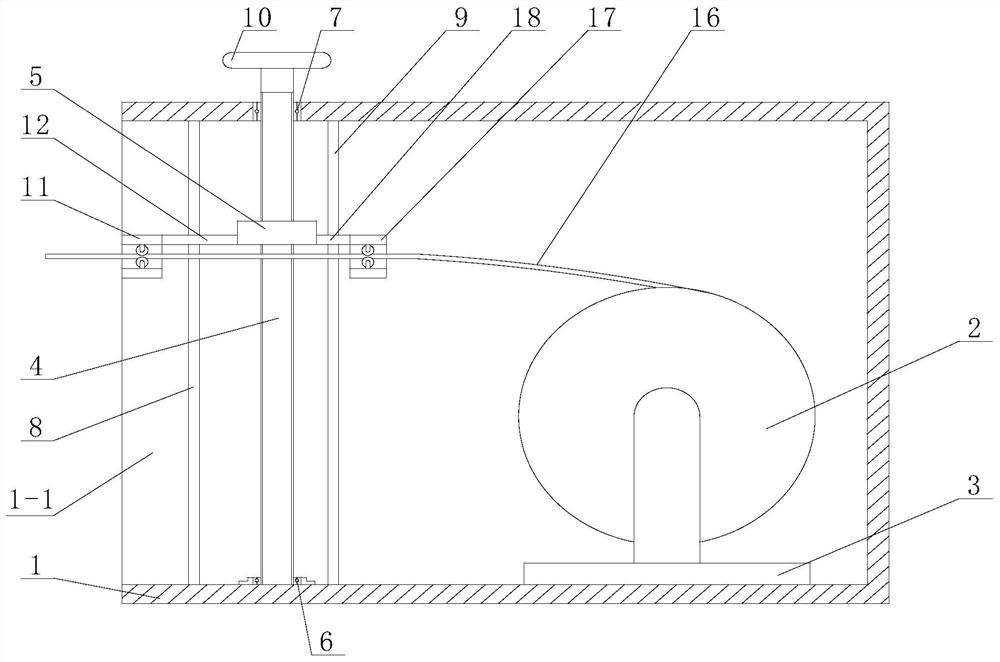
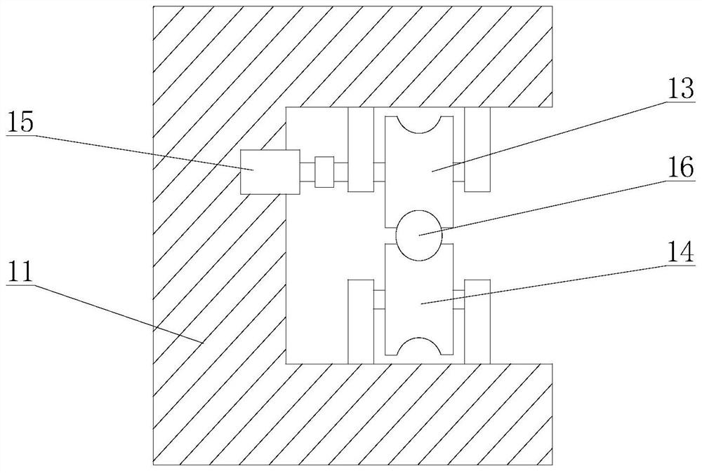
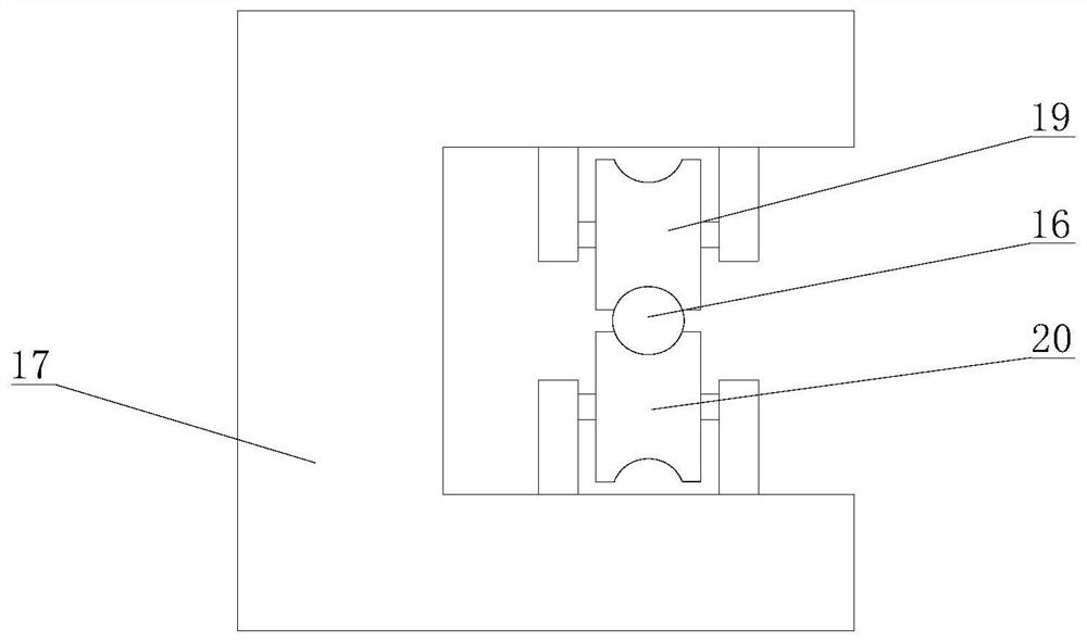
[0015] Specific implementation mode one: combine Figure 1 to Figure 3 This embodiment is described. The cable retracting device for an automatic laying cable vehicle described in this embodiment includes a housing 1, a cable reel 2, a base 3, a height adjustment mechanism, a cable guiding mechanism and a cable driving mechanism; The base 2 is fixedly installed in the housing 1, the cable reel 2 is installed on the base 3, the height adjustment mechanism is installed in the opening 1-1 of the housing 1, the cable driving mechanism and the cable The guide mechanism is sequentially installed on the height adjustment mechanism from outside to inside.

specific Embodiment approach 2

[0016] Specific implementation mode two: combination Figure 1 to Figure 3 This embodiment is described. The height adjustment mechanism of a cable retracting device for an automatic laying cable car in this embodiment includes a screw 4, a nut 5, a bearing seat 6, a bearing 7, a first guide rod 8 and a first guide rod 8. Two guide rods 9; the bearing 7 is embedded in the through hole at the top of the opening 1-1 of the housing 1, the bearing seat 6 is installed on the inner bottom surface of the opening 1-2 of the housing 1, and the upper end of the screw 4 is inserted Installed in the bearing 7, the lower end of the lead screw 4 is inserted into the bearing seat 6, the nut 5 is set on the lead screw 4, the first guide rod 8 is vertically arranged on the outside of the lead screw 4, and the first guide rod 8 The upper end is fixedly connected with the top surface in the housing 1, the lower end of the first guide rod 8 is fixedly connected with the bottom surface in the hous...

specific Embodiment approach 3

[0017] Specific implementation mode three: combination Figure 1 to Figure 3 To illustrate this embodiment, the height adjustment mechanism of the cable retracting device for an automatic cable laying vehicle in this embodiment further includes a rotating handle 10 , and the upper end of the lead screw 4 passes through the bearing 7 and is fixedly connected to the rotating handle 10 . Other components and connections are the same as those in the second embodiment.


PUM


Abstract

The invention discloses relates to a cable take-up and pay-off device, in particular to a cable take-up and pay-off device for an automatic cable laying vehicle. The invention aims to solve the problems that the position of a cable outlet of an existing automatic cable laying vehicle is fixed, the height cannot be adjusted, and the use is very inconvenient. The cable take-up and pay-off device comprises a shell, a cable winding drum, a base, a height adjusting mechanism, a cable guide mechanism and a cable driving mechanism, wherein the base is fixedly installed in the shell, the cable windingdrum is installed on the base, the height adjusting mechanism is installed in an opening of the shell, and the cable driving mechanism and the cable guide mechanism are sequentially installed on theheight adjusting mechanism from outside to inside. The invention belongs to the field of power equipment.

Description

technical field [0001] The invention relates to a cable retracting device, in particular to a cable retracting device for an automatic laying cable car, belonging to the field of electric equipment. Background technique [0002] A cable is made of one or more mutually insulated conductors and an outer insulating layer, which transmits power or information from one place to another. In order not to affect the design of the building, the cable is usually laid according to a preset route On the wall, achieve the purpose of neatness and beauty. The outlet position of the existing automatic laying cable car is fixed, and the height cannot be adjusted, which is very inconvenient to use. Contents of the invention [0003] In order to solve the problem that the exit position of the existing automatic cable laying car is fixed, the height cannot be adjusted, and it is very inconvenient to use, the present invention further proposes a cable retracting device for the automatic cable...

Claims


Application Information

Patent Timeline
IPC IPC(8): B65H75/42B65H75/44B65H57/14
CPCB65H57/14B65H75/425B65H75/4402B65H75/4457B65H75/4486B65H2701/34
Inventor 孙巍张健张德文韩思玮曲中直
Owner STATE GRID HEILONGJIANG ELECTRIC POWER CO LTD ELECTRIC POWER RES INST
Why Eureka
Try Eureka