
A Secondary Ejection Structure of Injection Mold Crank Slider

A crank-slider mechanism and crank-slider technology are applied in the field of injection molds, which can solve the problems of complex structure and high cost of secondary ejection molds, and achieve the effects of simple processing and assembly, low cost and high versatility

Active Publication Date: 2021-09-03
武汉华升源模具有限责任公司
View PDF9 Cites 0 Cited by
  • Summary
  • Abstract
  • Description
  • Claims
  • Application Information

AI Technical Summary

Problems solved by technology

[0004] The invention provides a secondary ejection structure and method of the crank slider of an injection mold, which solves the technical problem of the above-mentioned complex and high cost of the secondary ejection mold structure

Method used


Image

  • A Secondary Ejection Structure of Injection Mold Crank Slider
  • A Secondary Ejection Structure of Injection Mold Crank Slider
  • A Secondary Ejection Structure of Injection Mold Crank Slider

Examples


Embodiment Construction

[0027] The principles and features of the present invention are described below in conjunction with the accompanying drawings, and the examples given are only used to explain the present invention, and are not intended to limit the scope of the present invention. In the following paragraphs the invention is described more specifically by way of example with reference to the accompanying drawings. Advantages and features of the present invention will be apparent from the following description and claims. It should be noted that all the drawings are in a very simplified form and use imprecise scales, and are only used to facilitate and clearly assist the purpose of illustrating the embodiments of the present invention.

[0028] It should be noted that when a component is said to be "fixed" to another component, it can be directly on the other component or there can also be an intervening component. When a component is said to be "connected" to another component, it may be direc...


PUM


Abstract

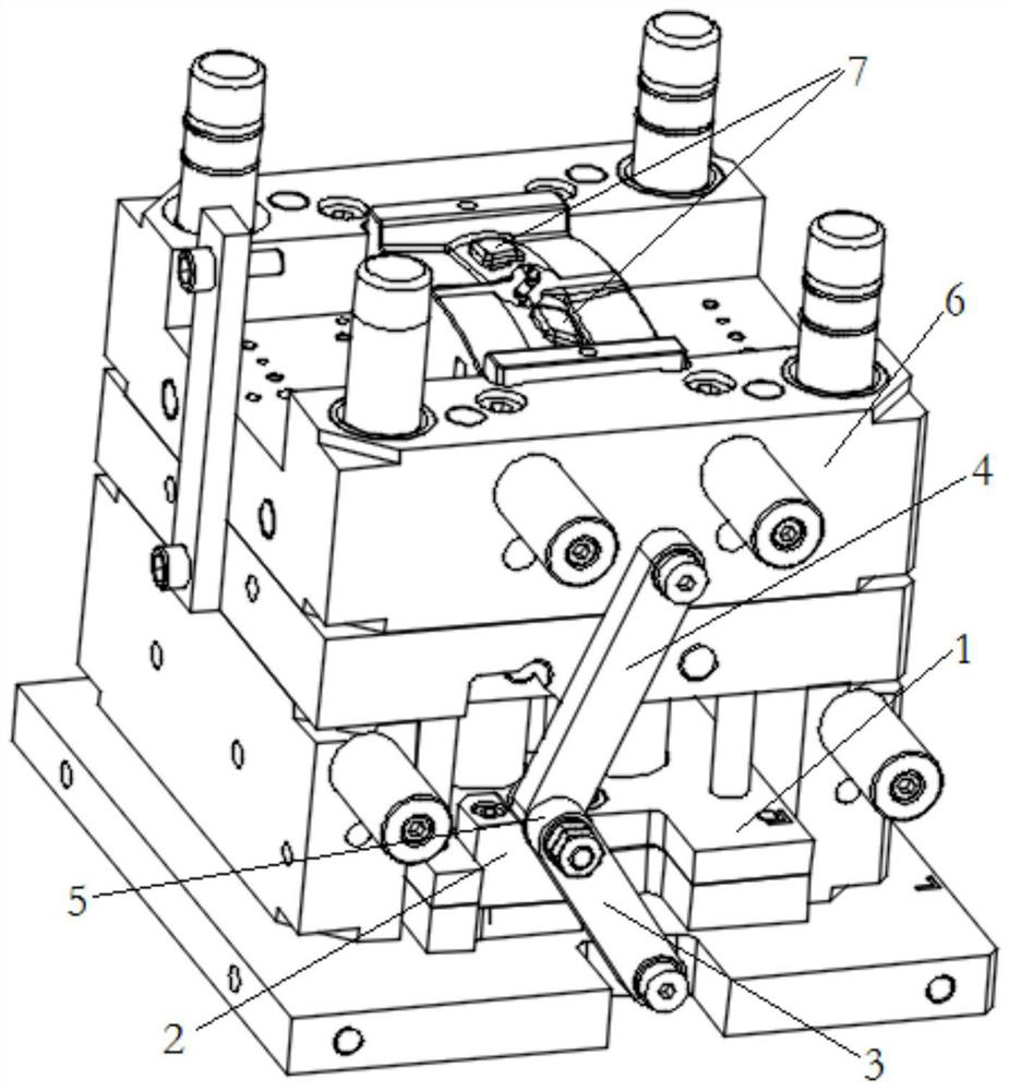
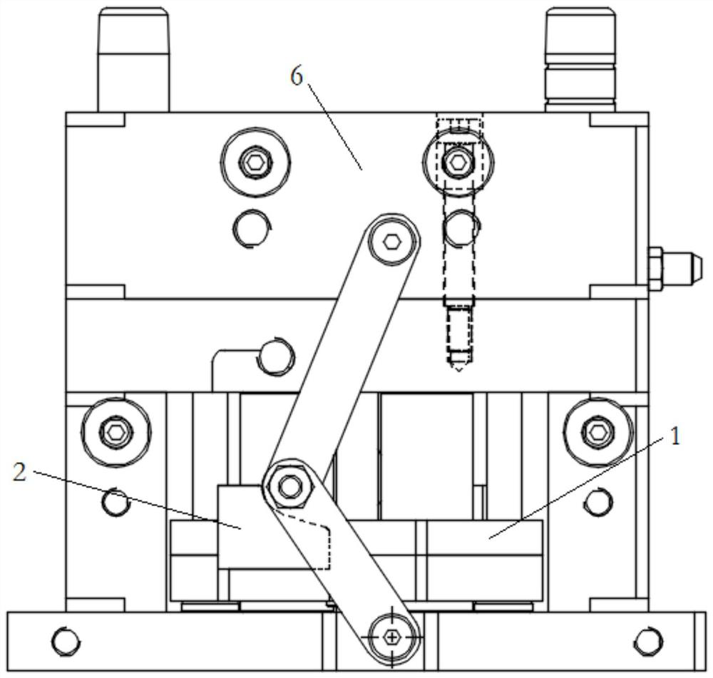
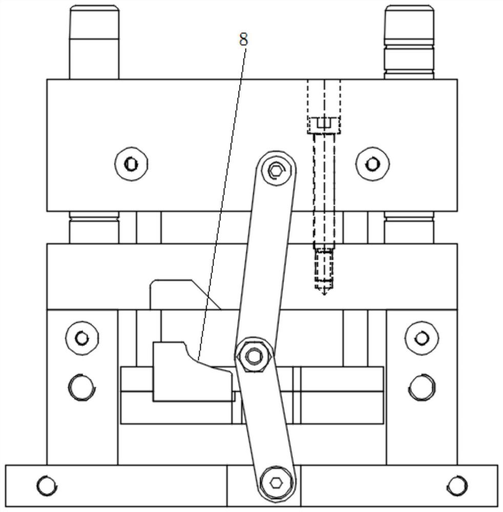
The invention relates to the technical field of injection molds, and relates to a secondary ejection structure and method of a crank slider of an injection mold, including a crank slider mechanism, a push plate for pushing a movable mold upward to eject a product to a first distance, Shifting block and thimble block; the slider crank mechanism includes a first connecting rod and a second connecting rod, one end of the first connecting rod is hinged with the base, the other end is hinged with one end of the second connecting rod through a hinge, and the other end of the second connecting rod is hinged. One end is hinged with the push plate; the hinge is slidable and located in the semi-crescent chute of the shifting block, the shifting block is fixedly connected with the thimble block, and the thimble block is fixed with a thimble for ejecting the product to the second distance. When the plastic product has a deep glue position on the movable mold side, the secondary ejection structure is simple and easy to realize product demoulding, and it has low cost, simple maintenance and high versatility. Achieve secondary ejection with fewer parts added. The processing and assembly of the added parts are easier. So as to achieve the effect of saving mold cost.

Description

technical field [0001] The invention relates to the technical field of injection molds, in particular to a secondary ejection structure of a crank slider of an injection mold. Background technique [0002] With the wide application of insert injection molds, the disadvantages of the original mode of manually placing inserts are becoming more and more prominent. In the industry, there are mold structures suitable for automatic placement of inserts, and the mold ejection system is to realize automation. The key is that in the technology of the same industry, after the injection mold ejects the insert product, the insert product remains in contact with the ejector pin in the ejection structure. Then, when the product moves horizontally with the material belt, it often The product is scratched or the thimble is broken, which greatly reduces the qualified rate of the product and increases the cost of mold maintenance. [0003] Due to the shape of the plastic part itself, the pro...

Claims


Application Information

Patent Timeline
Patent Type & Authority Patents(China)
IPC IPC(8): B29C45/40
CPCB29C45/4005B29C2045/4047
Inventor 董正科易申兵操向东
Owner 武汉华升源模具有限责任公司
Learn More