
Water pump

A water pump and pump wheel technology, applied in the direction of pumps, pump components, pump devices, etc., can solve problems such as rare earth metal obstruction, and achieve the effects of long service life, good heat transfer, and high vibration resistance

Pending Publication Date: 2021-03-09
HANON SYST EFP DEUT GMBH
View PDF13 Cites 0 Cited by
  • Summary
  • Abstract
  • Description
  • Claims
  • Application Information

AI Technical Summary

Problems solved by technology

However, the use of rare earth metals is hampered by fluids such that the rare earth elements may require additional packaging to prevent damage

Method used


Image

  • Water pump
  • Water pump

Examples


Embodiment Construction

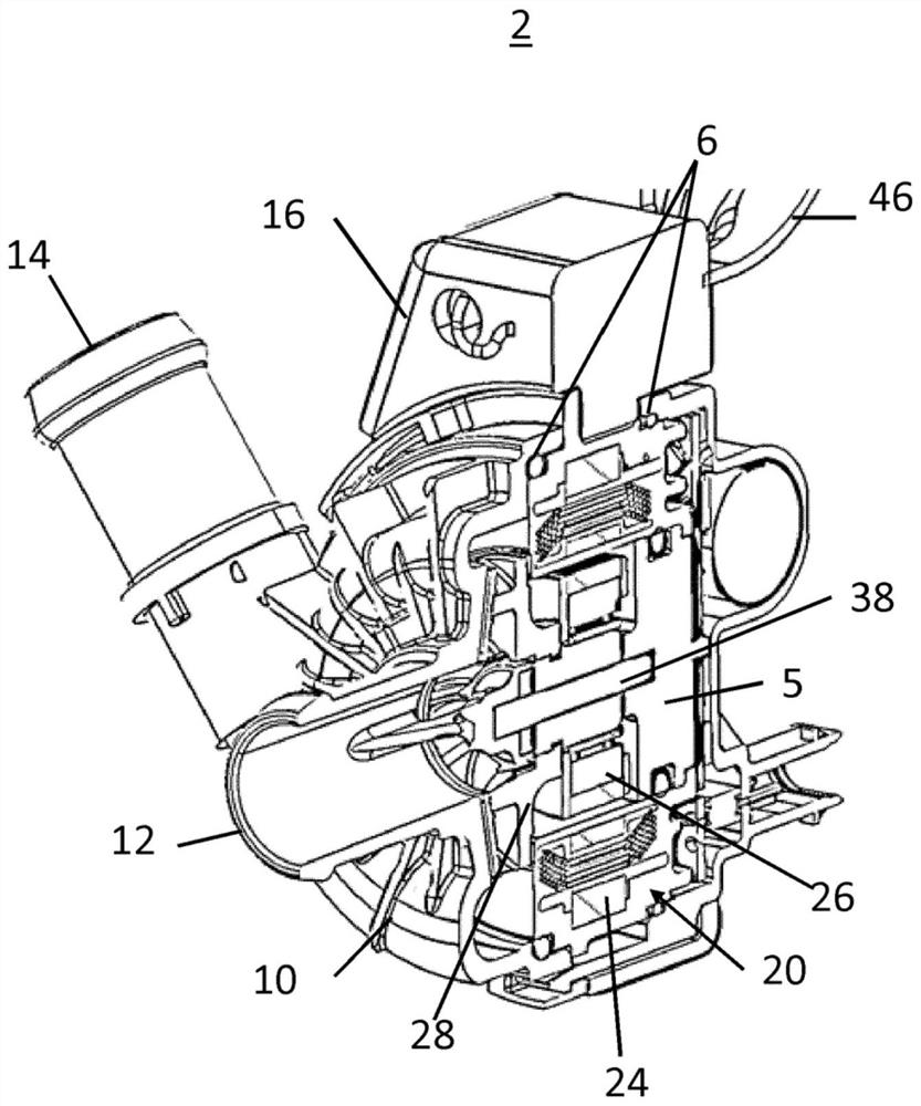
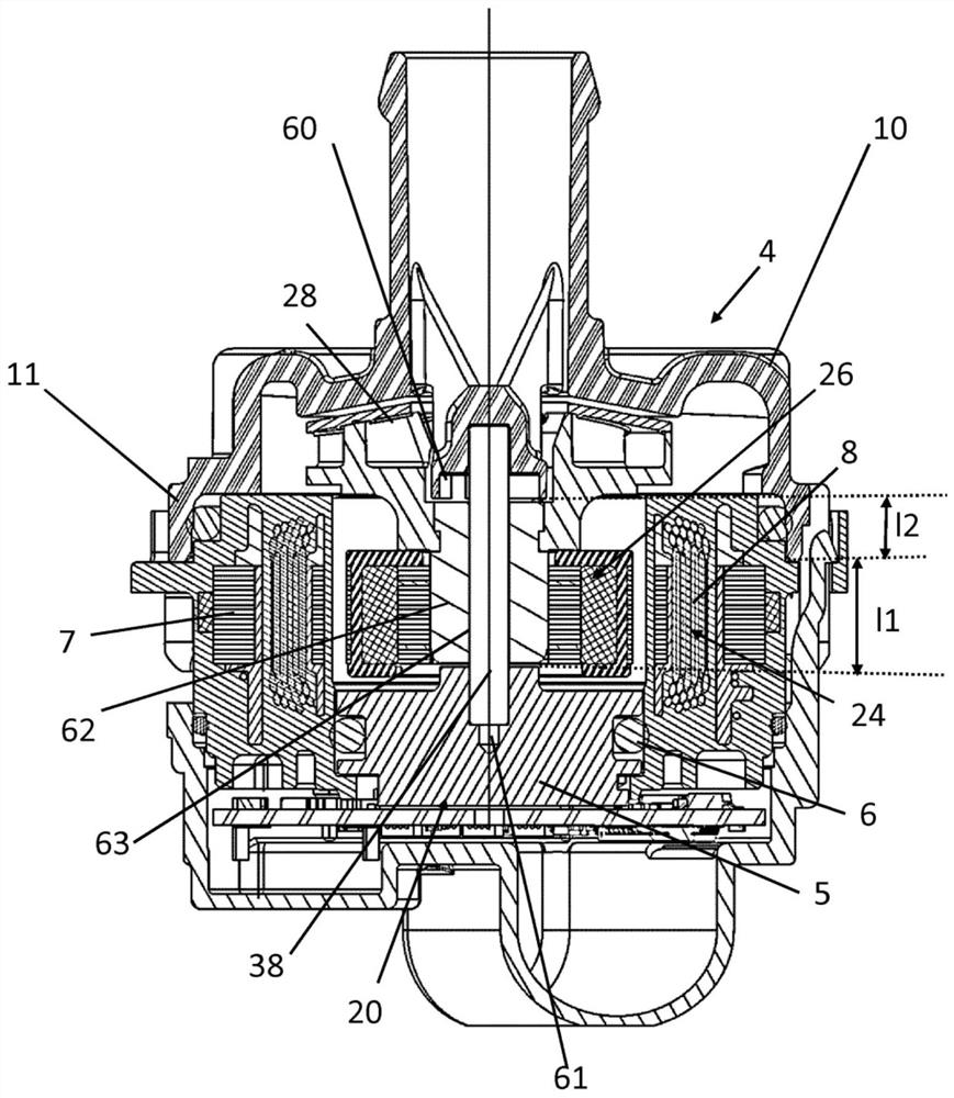
[0018] The water pump 2 comprises a screw 10 , a cover 20 and a fixing clip 22 which fixes the cover 20 and the screw 10 . The screw 10 includes an inlet 12 and an outlet 14 . The spiral part includes a power supply interface. The screw 10 is connected to the cover 20 via fixing clips or any other connection to form a cover 4 which surrounds the internal components and which comprises a power supply interface 16 for mounting a supply line 46 . Internal components of the water pump 2 include a stator 24 which in one embodiment is press fit into the housing 20 . A stator 24 surrounds a rotor 26 . The rotor 26 and stator 24 are separated by a magnetic air gap. The rotor 26 includes a pump wheel 28 for moving the fluid as it enters the inlet 12 . The impeller 28 moves fluid through the outlet 14 for use.

[0019] A preferred embodiment of the water pump is designed with a reduced number of components. The pump 2 has a shroud 20 combining different functions: said shroud defi...


PUM


Abstract

The invention relates to a water pump with an impeller which that is driven by an electric machine, comprising a housing cover and a coil with an inlet and an outlet, as well as comprising a cap, in which a stator and a rotor of the electric machine are housed, characterised in that the rotor is secured to a fixed shaft in the water pump, which has a bushing that is rotationally fixed to the shaft.

Description

technical field [0001] The invention relates to a water pump with a pump wheel driven by an electric motor, said water pump comprising a casing cover and a screw and a casing, said coil having an inlet and an outlet, in which casing is mounted the stator of the motor and fixed to the shaft on the rotor. Background technique [0002] A water pump usually consists of a stator and a rotor. The rotor is connected to the impeller to move the fluid. Fluid enters the pump through an inlet in the screw, contacts the impeller, and moves through an outlet in the screw. The rotor and stator are contained in a housing which is connected to the screw. Typically, the rotor and stator are separated by a magnetic air gap, and the rotor and stator contain rare-earth metals, making it possible to bridge the magnetic air gap between the rotor and stator so that the rotor rotates during use and the rotor, stator, or both The latter is isolated from the fluid during use and continues to func...

Claims


Application Information

Patent Timeline
IPC IPC(8): F04D13/06
CPCF04D13/0633F05B2230/22F04D13/0606F04D13/08F04D29/043F04D29/22F04D29/426F05D2230/14F05D2230/22F05D2230/90F05D2210/11F05D2240/50F05D2300/224F05D2300/43F05D2300/516F04D13/06F04D13/026F04D29/026
Inventor 埃内斯托·乔瓦尼·阿诺尔迪保罗·林科尔恩·毛里诺
Owner HANON SYST EFP DEUT GMBH
Learn More