
Cable construction equipment

A technology for construction equipment and cables, which is applied in the directions of cable laying equipment, cable installation, and ground cable installation, etc. It can solve the problems of mutual friction between cables and well edges, and achieve the effects of improving laying efficiency, good use effect, and simple structure

Inactive Publication Date: 2021-03-09
钱根新
View PDF7 Cites 6 Cited by
  • Summary
  • Abstract
  • Description
  • Claims
  • Application Information

AI Technical Summary

Problems solved by technology

If it is necessary to change the pulling direction of the cable puller on the ground when the actual road conditions do not allow, it will cause the cable to break away from the roller A and roller B in a fixed position, so that the cable and the well edge will rub against each other again. The phenomenon

Method used


Image

  • Cable construction equipment
  • Cable construction equipment
  • Cable construction equipment

Examples


Embodiment Construction

[0036] The accompanying drawings are all schematic diagrams of the implementation of the present invention, so as to understand the principle of structural operation. The specific product structure and proportional size can be determined according to the use environment and conventional technology.

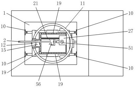
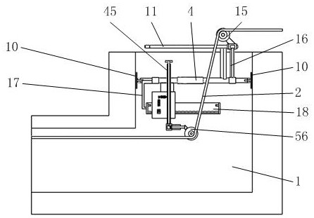
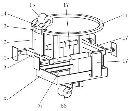
[0037] Such as figure 1 , 2 , 3, it includes a support rod A3, a telescopic rod structure 4, a foot 9, a guide ring 11, a sliding sleeve 12, a roller A15, a fixed plate B17, a support frame 18, a guide rod 21, a slide rod 45, and a transmission case 48 , shaft sleeve 49, shaft A50, shaft B54, roller B56, among which image 3 , 5 As shown, the two support rods A3 are connected by two telescopic rod structures 4 whose lengths are symmetrically distributed and can be locked. The two support rods A3 are symmetrically installed with four supporting feet 9 supporting the side wall of the shaft of the cable shaft 1 . Such as figure 2 , 3 As shown, a guide ring 11 with a vertical c...


PUM


Abstract

The invention belongs to the field of cable construction, and particularly relates to cable construction equipment which comprises support rods A, telescopic rod structures, supporting legs, guide rings, sliding sleeves, a roller A, a fixing plate B, a supporting square frame, guide rods, sliding rods, a transmission shell, shaft sleeves, shafts A, shafts B and a roller B, wherein the two supportrods A are connected through the two symmetrically-distributed telescopic rod structures with the length capable of being locked, four supporting legs for supporting and pressing the vertical shaft wall of a cable well are symmetrically mounted on the two support rods A. By adjusting the position of the roller A at the outlet of the vertical shaft of the cable well and the position of the roller Bat the corner of the cable well, a cable supported and guided by the roller B and the roller A in sequence is supported away from the well edge of the cable well, and cable skin damage caused by friction of the cable at the corner of the cable well in a traditional cable construction mode is avoided, and the quality of cable construction and the safety of cable operation after cable constructionare ensured.

Description

technical field [0001] The invention belongs to the field of cable construction, in particular to a cable construction equipment. Background technique [0002] In the cable laying construction of municipal engineering, few effective auxiliary facilities are used for the laying of cables in cable wells to prevent the cable from being pulled due to friction with the edge of the cable well or the corner in the well during the movement. The skin is damaged and ruptured, which often leads to problems during the operation of the cable after laying. The damage of the cable skin directly leads to the shortening of the service life of the cable and the safety of the cable operation. [0003] The published publication number "103956692A" of "a special bracket for interspersed cables in municipal engineering" only solves the situation that the cables are worn out when the cables are pulled in the direction consistent with the running direction of the cables downhole. If it is necessar...

Claims


Application Information

Patent Timeline
Patent Type & Authority Applications(China)
IPC IPC(8): H02G1/06H02G9/02
CPCH02G1/06H02G9/02
Inventor 钱根新
Owner 钱根新
Learn More