Wire arrangement device for power distribution cabinet
A cable arrangement and power distribution cabinet technology, which is applied in substation/power distribution device housing, busbar/line layout, substation/switch layout details, etc., can solve problems such as troublesome maintenance, damage to power distribution cabinet, short circuit, etc., and achieve benefits Retractable and easy to install
- Summary
- Abstract
- Description
- Claims
- Application Information
AI Technical Summary
Problems solved by technology
Method used
Image

Examples
Embodiment 1
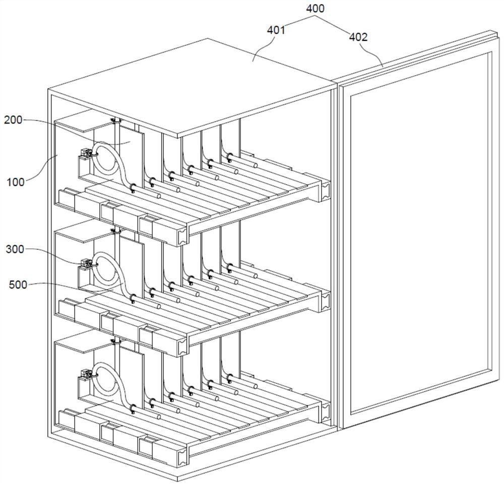
[0041] refer to Figure 1 to Figure 3 , which is the first embodiment of the present invention, this embodiment provides a cable arrangement for a power distribution cabinet, including a frame 100, a baffle 200 and a cable assembly 300;
[0042] The frame 100 is fixed in the cabinet body 401 of the power distribution cabinet 400, and the frame 100 is located on the inner wall away from the opening of the cabinet body 401. The space between the frame 100 and the opening of the cabinet body 401 is used for installing electrical devices, and the cables connected to the electrical devices 500 is located at the rear of the electrical components and is arranged through this cable arrangement device; several baffles 200 divide the frame 100 into several cable arrangement spaces along the width direction of the cabinet body 401, and each cable arrangement space can be equal or unequal in width Width, determined according to the size of the actually installed electrical components, eac...
Embodiment 2
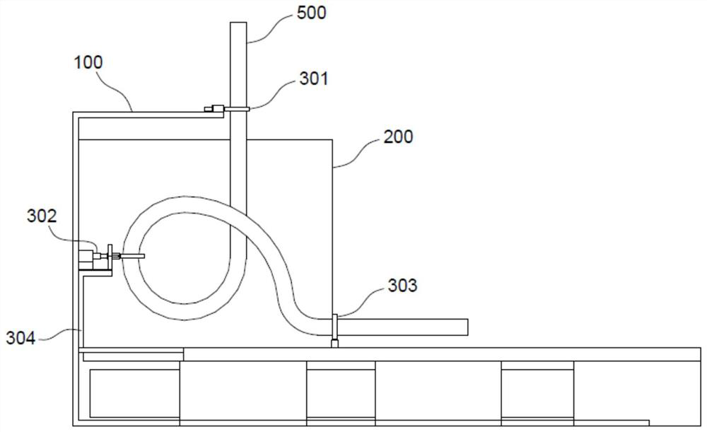
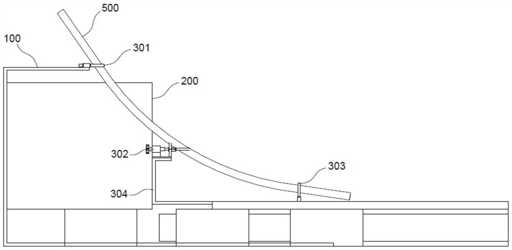
[0050] refer to Figure 2 to Figure 5 , this embodiment is different from the above-mentioned embodiment in the specific structure of the second limit assembly 302. It can be seen from Embodiment 1 that the second limit assembly 302 needs to have a rotatable function, and the second limit assembly 302 includes a base 302- 1 and a binding band 302-2, the binding band 302-2 is used to be fixedly connected with the cable 500; the binding band 302-2 is connected to the base 302-1 through the connecting piece 302-3 in rotation, and the binding band 302-2 is tightly bound The cable 500, the connection between the cable 500 and the binding belt 302-2 at this time can be rotated on the base 302-1 through the connecting piece 302-3, when the mounting base 304 moves into the moving space, the first limit When the component 301 is located between the second limiting component 302 and the third limiting component 303, the connection between the cable 500 and the binding band 302-2 is rota...
Embodiment 3
[0053] refer to Figure 6 to Figure 9 The difference between this embodiment and the above-mentioned embodiment is that the two ends of the binding band 302-2 are provided with limiting helical teeth S1 on the same side, and the inclination direction of the limiting helical teeth S1 is the same, and the limiting helical teeth at both ends of the binding band 302-2 S1 can be locked with each other; one end of the binding band 302-2 is fixed, the other end of the binding band 302-2 is bypassed by the cable 500 and is close to the fixed end of the binding band 302-2, and the two ends of the binding band 302-2 are connected to each other. The limiting helical teeth S1 are interlocked to limit the cable 500 in the annular space of the binding band 302-2;
[0054] In order to enable the binding band 302-2 to bind the cable 500 tightly, the extension 302-3-2 is provided with an accommodating cavity N1 that can accommodate both ends of the binding band 302-2 at the same time, and the ...
PUM
 Abstract
Description
Claims
Application Information
 - R&D
- Intellectual Property
- Life Sciences
- Materials
- Tech Scout
- Unparalleled Data Quality
- Higher Quality Content
- 60% Fewer Hallucinations
Browse by: Latest US Patents, China's latest patents, Technical Efficacy Thesaurus, Application Domain, Technology Topic, Popular Technical Reports.
© 2025 PatSnap. All rights reserved.Legal|Privacy policy|Modern Slavery Act Transparency Statement|Sitemap|About US| Contact US: help@patsnap.com