
Building construction cable rack based on reciprocating rotation

A technology of building construction and reciprocating rotation, which is applied to the installation of cables, cable installation devices, electrical components, etc., and can solve problems such as wasting manpower, cable twisting, and reducing the speed of cable twisting

Inactive Publication Date: 2021-03-09
成月香
View PDF0 Cites 4 Cited by
  • Summary
  • Abstract
  • Description
  • Claims
  • Application Information

AI Technical Summary

Problems solved by technology

[0002] The cable rack used in building construction supports the cable and twists the cable at the same time. At present, when the cable rack is twisted to pick up the cable, the twisting reel is directly twisted by the motor rotation. When the cable is hooked and difficult to pull, the cable can only be forcibly twisted through the twisting reel, which is easy to twist the cable, or use manual handling, which wastes manpower and reduces the speed of cable twisting

Method used


Image

  • Building construction cable rack based on reciprocating rotation
  • Building construction cable rack based on reciprocating rotation
  • Building construction cable rack based on reciprocating rotation

Examples


Embodiment 1

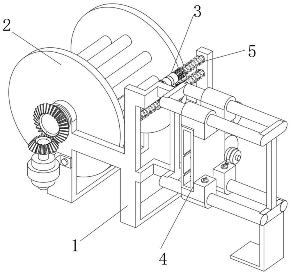
[0054] see Figure 1-Figure 13 As shown, a building construction cable rack based on reciprocating rotation is provided, including a cable winch 1, a winch device 2 is provided inside one end of the cable winch 1, and a position close to the top of the cable winch 1 is provided. Cable limiting device 3, a side pulling device 4 is provided on the end of the cable winch frame 1 away from the winch device 2;

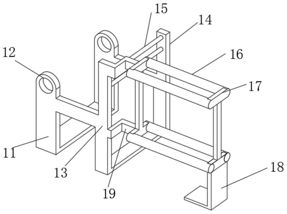
[0055] The cable winch 1 includes a U-shaped U-shaped frame 11, one side of the U-shaped frame 11 is fixedly connected with a bottom support frame 13 for support, and the left and right sides of the upper end of the bottom support frame 13 are fixedly connected with a square upper fixed frame. Plate 14, two upper fixed plates 14 are fixedly connected with two cylindrical sliding columns 15 arranged up and down, and the side of the sliding column 15 away from the U-shaped frame 11 near the edge is symmetrically arranged with two horizontal columns up and down. The set cylin...


PUM


Abstract

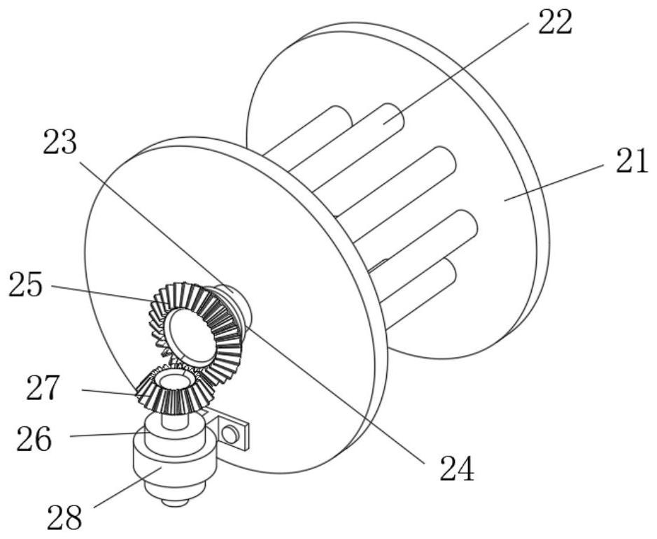
The invention relates to the technical field of building construction, in particular to a building construction cable rack based on reciprocating rotation. The building construction cable rack comprises a cable stranding rack, a stranding device is arranged in one end of the cable stranding rack, a cable limiting device is arranged at the position, close to the top, in the cable stranding rack, and a side pulling device is arranged at the end, away from the stranding device, of the cable stranding rack. The twisting device comprises two circular stranding discs, multiple cylindrical winding columns are fixedly connected to the side wall between the two stranding discs in an annular arrangement manner, the cable limiting device comprises two middle limiting devices which are symmetrically arranged up and down, and side limiting devices are arranged on the two sides of the two middle limiting devices. The side pulling device comprises a side pulling fixed shell, sliding fixed devices arearranged at the upper end and the lower end of the side pulling fixed shell in a bilateral symmetry manner, and a side pulling driving device is arranged in the side pulling fixed shell. The buildingconstruction cable rack mainly solves the problem that when a cable is hooked and is not easy to pull, the cable is prone to being damaged when the cable is stranded by the stranding discs.

Description

technical field [0001] The invention relates to the technical field of building construction, in particular to a building construction cable rack based on a reciprocating rotation type. Background technique [0002] The cable rack used in building construction supports the cable when it is in use, and also twists the cable. At present, when the cable rack is twisted to get the cable, the twisting reel is directly twisted by the motor rotation. When the cable is hooked and difficult to pull, the cable can only be forcibly twisted through the twisting reel, which is easy to twist the cable, or it can be handled manually, which wastes manpower and reduces the speed of cable twisting. Contents of the invention [0003] The object of the present invention is to provide a building construction cable rack based on reciprocating rotation, so as to solve the problems raised in the above-mentioned background technology. [0004] In order to achieve the above object, a reciprocating...

Claims


Application Information

Patent Timeline
IPC IPC(8): B65H54/44B65H57/10B65H57/26B65H51/00H02G1/00
CPCB65H51/00B65H54/44B65H57/10B65H57/26H02G1/00
Inventor 成月香
Owner 成月香
Learn More