Separated buffer

A buffer and separate technology, which is applied in the field of buffer devices, can solve the problems of decoupling of the release claw, low stability, and unstable position of the release claw.

Pending Publication Date: 2021-03-02
SUZHOU SHENGDE PRECISION ELECTRIC
View PDF0 Cites 0 Cited by
  • Summary
  • Abstract
  • Description
  • Claims
  • Application Information

AI Technical Summary

Problems solved by technology

[0002] In the existing sliding door buffer devices on the market, when the lever pulls the release claw to move outward, it generally relies on the pulling force of the lever to force the release claw to rotate to release the lever. The service life is not long, and the release claw is released. There will be a small rebound after the dial, which makes the position of the release claw not fixed. When the dial enters the release claw again, there will be a problem of decoupling, and the stability is not high.

Method used


Image

  • Separated buffer
  • Separated buffer
  • Separated buffer

Examples


Embodiment Construction

[0018] The following will clearly and completely describe the technical solutions in the embodiments of the present invention with reference to the accompanying drawings in the embodiments of the present invention. Obviously, the described embodiments are only some of the embodiments of the present invention, not all of them. Based on the embodiments of the present invention, all other embodiments obtained by persons of ordinary skill in the art without making creative efforts belong to the protection scope of the present invention.

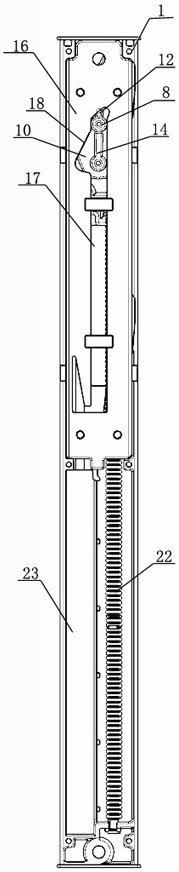
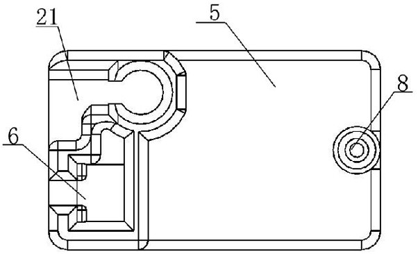
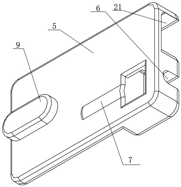
[0019] see Figure 1-8 , a separate buffer device provided by the present invention includes an oil pressure housing, a slider guide rail is provided in the middle of the oil pressure housing, an oil pressure groove is provided on one side of the slider guide rail, and an oil pressure groove is provided on the other side of the oil slider guide rail. A spring groove is provided on the side, a slider is provided on the hydraulic housing, a spring ...


PUM


Abstract

The invention discloses a separated buffer. The separated buffer comprises an oil pressure shell, wherein a sliding block guide rail is arranged in the middle of the oil pressure shell; a sliding block is arranged on the oil pressure shell; a release claw is arranged above the sliding block; a column shifting hole is formed in the release claw; a boss is arranged at one end of the column shiftinghole; a rotating hole is formed in the other end of the boss; the rotating hole is rotationally connected with a release claw fixing column; a fixing plate guide column is arranged at the other end ofthe rotating hole; a reinforcing guide column is arranged on one side of the fixing plate guide column; a fixing plate is arranged above the release claw; a release claw sliding rail is arranged in the middle of the fixing plate; an inclined plane turning hole is formed in the top of the release claw sliding rail; a reinforcing sliding rail is arranged on one side of the release claw sliding rail; and a hole is formed in the top end of the reinforcing sliding rail. The whole device is more powerful in limiting function and not prone to damage, the door opening tension is lower, the unhookingrisk is reduced, and the service life is prolonged.

Description

technical field [0001] The invention relates to a buffer device, in particular to a separate buffer. Background technique [0002] In the existing sliding door buffer devices on the market, when the lever pulls the release claw to move outward, it generally relies on the pulling force of the lever to force the release claw to rotate to release the lever. The service life is not long, and the release claw is released. There will be a small rebound after the dial, so that the position of the release claw is not fixed. When the dial enters the release claw again, there will be a problem of decoupling, and the stability is not high. Contents of the invention [0003] The object of the present invention is to provide a separate buffer to solve the above problems. [0004] In order to achieve the above object, the present invention provides the following technical solutions: a separate buffer, including a hydraulic housing, a slider guide rail is provided in the middle of the h...

Claims


Application Information

Patent Timeline
Patent Type & Authority Applications(China)
IPC IPC(8): E05F5/08
CPCE05F5/003E05Y2900/132
Inventor 廖瑞忠廖柏闵
Owner SUZHOU SHENGDE PRECISION ELECTRIC
Why Eureka
Try Eureka