Internal fixation device for osteoporotic fracture treatment and using method thereof

A technology for osteoporosis and fixation devices, applied in internal fixators, fixators, internal bone synthesis, etc., can solve the problems of reducing device practicability, reducing device functionality, inconvenient bone plate pre-fixation, etc., to improve practicability , easy to operate, to ensure the effect of the fixed effect

Inactive Publication Date: 2021-03-02
欧阳晓
View PDF0 Cites 1 Cited by
  • Summary
  • Abstract
  • Description
  • Claims
  • Application Information

AI Technical Summary

Problems solved by technology

[0003] The existing internal fixation devices for the treatment of osteoporotic fractures require medical staff to fix the device on the fracture of the patient by hand during use, which leads to a smaller operating space for the medical staff, making it inconvenient for the medical staff to operate and lowering the device. Practicality, secondly, the existing internal fixation devices for the treatment of osteoporotic fractures are inconvenient for medical staff to locate and nail because the environment at the fracture site is relatively dark during use, which reduces the fixation effect of the device. In addition, The existing internal fixation devices for the treatment of osteoporotic fractures cannot be adjusted according to the patient's spine specifications during the process of fixing the bone plate, which makes it inconvenient to pre-fix the bone plate and reduce the functionality of the device. Therefore, there is an urgent need for a Internal fixation device for the treatment of osteoporotic fractures to solve existing problems

Method used


Image

  • Internal fixation device for osteoporotic fracture treatment and using method thereof
  • Internal fixation device for osteoporotic fracture treatment and using method thereof
  • Internal fixation device for osteoporotic fracture treatment and using method thereof

Examples


Embodiment Construction

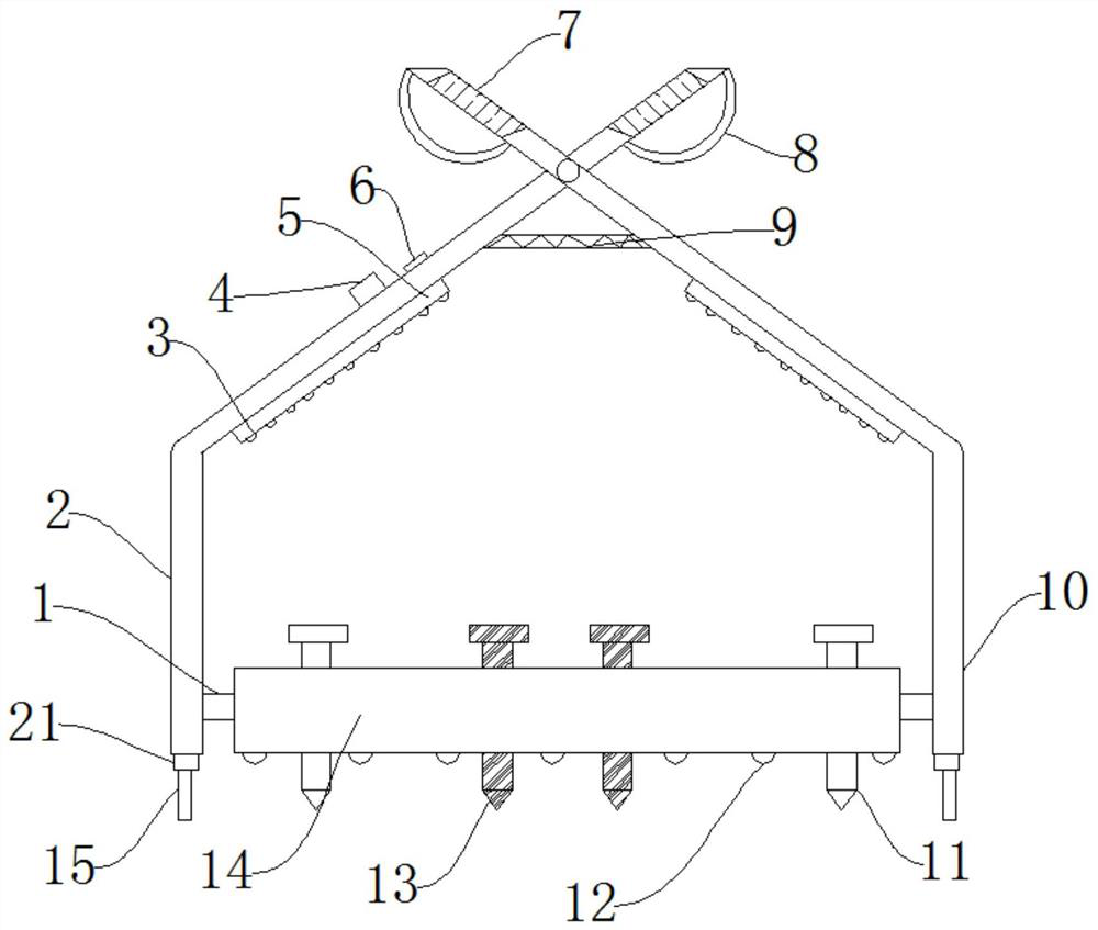
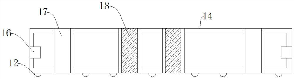
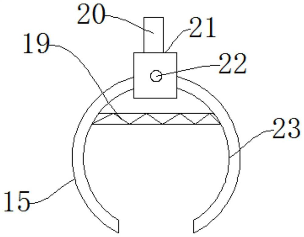
[0033] The present invention will be further described below in conjunction with accompanying drawing:

[0034] Such as Figure 1-Figure 4 As shown, an internal fixation device for treating osteoporotic fractures includes a bone plate 14, a fixing hole 16, a connecting rod one 2 and a connecting rod two 10, and the two side walls of the bone plate 14 are provided with the described Fixing holes 16, one side of the bone plate 14 is provided with the first connecting rod 2, the other side of the bone plate 14 is provided with the second connecting rod 10, the first connecting rod 2 and the second connecting rod 10 The bottom end of the side wall is provided with a fixed column 1, and the upper end of the side wall of the connecting rod one 2 and the connecting rod two 10 is provided with a handle 8, and a rubber sleeve 7 is provided on one side of the handle 8. A return spring 9 is arranged between the connecting rod one 2 and the connecting rod two 10, a battery pack 25 is arr...


PUM


Abstract

The invention discloses an internal fixation device for osteoporotic fracture treatment and a using method thereof. The internal fixation device comprises a bone plate, fixing holes, first connectingrods and second connecting rods, the fixing holes are formed in the two side walls of the bone plate, the first connecting rods are arranged on one side of the bone plate, the second connecting rods are arranged on the other side of the bone plate, and fixing columns are arranged at the bottom ends of one side walls of the first connecting rods and the second connecting rods. The device has the beneficial effects that: by arranging the first connecting rods and the second connecting rods, the first connecting rods and the second connecting rods can clamp and fix the bone plate, then the bone plate is placed in the body of a patient, the bone plate can be fixed from the outside, the operation space of medical staff is not occupied, the operation of the medical staff is facilitated, and thepracticability of the device is improved; and by arranging a lamp holder, a switch and an LED lamp, the LED is controlled by the switch to work, so that the operation environment of medical staff is illuminated, the medical staff can position and nail the bone plate conveniently, and the fixing effect of the device is guaranteed.

Description

technical field [0001] The invention relates to the technical field of medical instruments and devices, in particular to an internal fixation device for treating osteoporotic fractures and a method for using the same. Background technique [0002] Osteoporosis is a systemic bone disease in which bone density and bone quality decrease due to various reasons, bone microstructure is destroyed, bone fragility increases, and fractures are prone to occur. Osteoporosis is divided into two categories: primary and secondary. When treating osteoporosis, it needs to be fixed by internal fixation devices. [0003] The existing internal fixation devices for the treatment of osteoporotic fractures require medical staff to fix the device on the fracture of the patient by hand during use, which leads to a smaller operating space for the medical staff, making it inconvenient for the medical staff to operate and lowering the device. Practicality, secondly, the existing internal fixation devi...

Claims


Application Information

Patent Timeline
IPC IPC(8): A61B17/68A61B17/70
CPCA61B17/68A61B17/7059A61B17/7074
Inventor 欧阳晓
Owner 欧阳晓
Why Eureka
Try Eureka