A cross-scale numerical simulation method based on the wall slip effect of micro-nano grooves

A numerical simulation and wall slip technology, applied in electrical digital data processing, instrumentation, design optimization/simulation, etc., can solve the problems of difficult numerical simulation of global flow field, expensive calculation cost, etc., and achieve the effect of improving design and calculation efficiency

Active Publication Date: 2022-05-20
FUDAN UNIV
View PDF9 Cites 0 Cited by
  • Summary
  • Abstract
  • Description
  • Claims
  • Application Information

AI Technical Summary

Problems solved by technology

[0004] However, in the actual configuration, due to the huge scale difference between the surface structure of the micro / nano grooves and the airfoil, it is difficult to directly describe the global flow field with a large number of grids for numerical simulation, which requires expensive calculation costs

Method used


Image

  • A cross-scale numerical simulation method based on the wall slip effect of micro-nano grooves
  • A cross-scale numerical simulation method based on the wall slip effect of micro-nano grooves
  • A cross-scale numerical simulation method based on the wall slip effect of micro-nano grooves

Examples


Embodiment 1

[0040] The invention provides a cross-scale numerical simulation method based on the micro-nano groove wall slip effect.

[0041] Step (1): Regional division of the global flow field

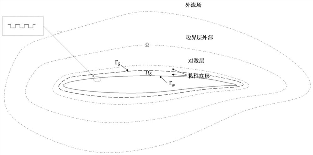
[0042] Such as figure 1 As shown, in order to simulate the global flow field Ω of an airfoil with micro-nano grooved surface structure, we propose a domain decomposition method to solve this multi-scale problem. The global flow field is divided into the viscous bottom layer, the logarithmic layer, the outer boundary layer, and the outer flow field. The actual boundary of the flow field is Γ w , denoted with an artificial internal boundary Γ δ (within the first grid point on the wall) the microscopic near-wall region that lies within the viscous substratum. The global problem is then decomposed into two problems: 1) Based on the microscopic simulation data, the microscopic near-wall region is replaced by a proxy model of the micro-nano groove surface structure. 2) The modified wall boundar...


PUM


Abstract

The invention belongs to the technical field of cross-scale numerical simulation, and specifically relates to a cross-scale numerical simulation method based on the sliding effect of micro-nano groove walls. The present invention first utilizes the particle Boltzmann method considering the rarefaction effect to simulate the flow in the near-wall region, trains the replacement model based on a large amount of simulated data, and accurately reproduces the flow characteristics of the micro-nano groove surface structure through the model. Then the proxy model is applied as a modified wall condition on the boundary of the macro model, and the subsonic and transonic flows are numerically simulated by the RANS or LES method in the macro simulation, so as to apply the micro-nano groove structure for the aircraft design field. Control provides simulation methods that enable cross-scale simulations and greatly improve computational efficiency.

Description

technical field [0001] The invention belongs to the technical field of cross-scale numerical simulation, and in particular relates to a cross-scale numerical simulation method based on the sliding effect of micro-nano groove walls. Background technique [0002] In recent decades, in order to achieve the goal of energy saving and emission reduction, fluid mechanics scholars have been devoting themselves to the development of effective drag reduction methods in engineering applications. Inspired by the tooth-like ribs on the surface of shark skin, microscale drag-reducing structures have attracted much attention as a passive flow control technique that does not require additional equipment or energy consumption. This textured surface structure delays the transition from laminar to turbulent flow by altering the flow near the wall, thereby reducing surface friction. [0003] The micro-nano-scale groove structure infiltrates in the viscous bottom layer of the boundary layer, wh...

Claims


Application Information

Patent Timeline
Patent Type & Authority Patents(China)
IPC IPC(8): G06F30/28G06F113/08
CPCG06F30/28G06F2113/08Y02T90/00
Inventor 孙刚王聪王立悦王舒悦游波
Owner FUDAN UNIV
Why Eureka
Try Eureka