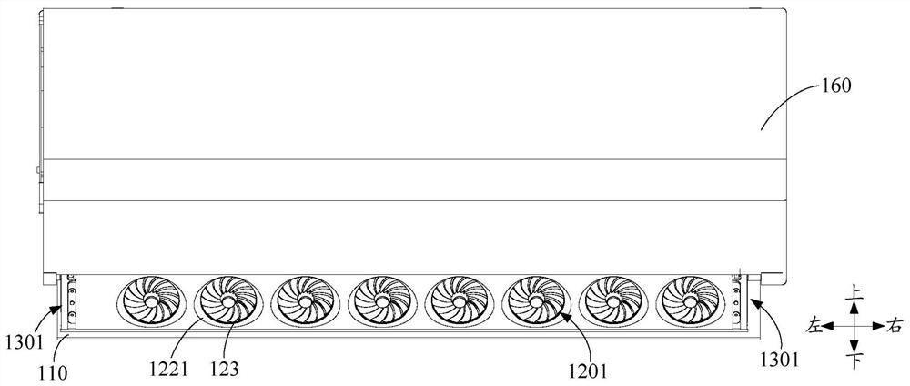
Air conditioner
An air conditioner and air-conditioning technology, which is applied in air-conditioning systems, space heating and ventilation, space heating and ventilation details, etc., can solve problems such as insufficient cooling capacity, meet cooling capacity requirements, improve room temperature uniformity, and avoid The effect of opening the angle too large
- Summary
- Abstract
- Description
- Claims
- Application Information
AI Technical Summary
Problems solved by technology
Method used
Image
Examples
Embodiment 1
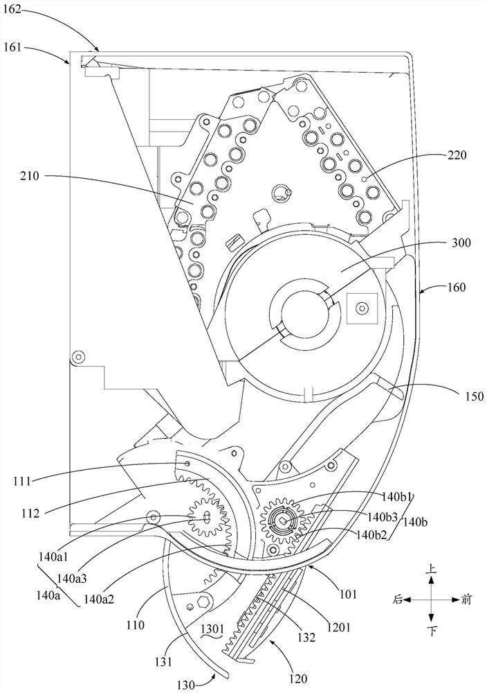
[0075] Such as image 3 As shown, in addition to the features of the above embodiments, it is further defined that: the cavity 130 includes: a first side wall 131 and a second side wall 132, the first side wall 131 is formed as a part of the wind deflector 110; The wall 132 is formed as a part of the diffuser assembly 120 , and the first side wall 131 and the second side wall 132 overlap and join together to form an angle-shaped cavity 130 . That is, the cavity 130 is formed by combining the first side wall 131 of the air deflector 110 and the second side wall 132 of the air diffuser assembly 120, so that the wind deflector 110 and the air diffuser assembly 120 can be flexibly adjusted to achieve a windless mode Switching, control is more convenient. The structure is simple, easy to process, low in cost, and requires little modification of the structure of the wind deflector 110. The wind deflector 110 and the air diffuser assembly 120 can be used for the purpose of wind defl...
Embodiment 2
[0080] Such as Figure 4 , Figure 5 , Figure 7 and Figure 8 As shown, in addition to the features of any of the above-mentioned embodiments, it is further defined that: the wind deflector 110 and the diffuser assembly 120 are respectively movable (for example, the wind deflector 110 and the diffuser assembly 120 are respectively movably connected with the housing 160 to realize Respectively movable setting), and drive device 140 is respectively provided to drive, at least one of the wind deflector 110 and the wind diffuser assembly 120 moves, so that the wind deflector 110 and the wind diffuser assembly 120 are combined or disassembled. The wind deflector 110 and the diffuser assembly 120 are designed to be movable so that the state switching between the two can be combined or disassembled. Influenced by the shape, it is used solely for wind-guiding purposes, and it is convenient for the product to switch between multiple modes.
[0081] Optionally, the wind deflector 1...
Embodiment 3
[0092] Such as image 3 and Figure 6 As shown, in addition to the features of any of the above-mentioned embodiments, it is further defined that the air conditioner also includes a guide structure, and the air deflector 110 is provided with a guide portion 112, and the guide structure is slidably connected to the guide portion 112, and the air guide plate 110 swipe to guide. In this way, the movement direction of the wind deflector 110 is easier to control, the control process is simplified, and the precision of wind deflector is improved.
[0093] For example, the guide structure is an arc-shaped guide groove arranged in the air vessel, and the guide part 112 is a guide column arranged on the wind deflector 110. The guide column extends into the guide groove and slides along the guide groove. The motion trajectory of the wind deflector 110 is controlled according to the shape and size of the shape, thereby controlling the motion direction of the wind deflector 110 . Of co...
PUM
 Abstract
Description
Claims
Application Information
 - R&D Engineer
- R&D Manager
- IP Professional
- Industry Leading Data Capabilities
- Powerful AI technology
- Patent DNA Extraction
Browse by: Latest US Patents, China's latest patents, Technical Efficacy Thesaurus, Application Domain, Technology Topic, Popular Technical Reports.
© 2024 PatSnap. All rights reserved.Legal|Privacy policy|Modern Slavery Act Transparency Statement|Sitemap|About US| Contact US: help@patsnap.com


